Week-7 Challenge: DC Motor Control
1. A. Explain a MATLAB demo model named ‘Speed control of a DC motor using BJT H-bridge’.
B. Comment on the armature current shoot-up from the scope results.
C. Refer to the help section of ‘The Four-Quadrant Chopper DC Drive (DC7) block’. Compare it with the H-bridge model.
ANS:-
AIM:- MODIFY THE MODEL SUCH THAT THE ARMATURE CURRENT DOESENT SHOOTUP WHEN THE MOTOR CHANGES DIRECTION FROM FORWORD TO REVERSE.
BJT-H BRIDGE:-
The bipolar junction transistor(BJT) used for power switching application.When it is conducting a forword voltage is developed between collector & emmitor(in the range of 1V).
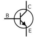
SO,IGBT block can be used to model the BJT device.The IGBT block does not simulate the gate current controlling the BJT. The switch is conrolled by simulink signal(1/0).The DC motor uses the pre-set model (5hp 24v 1750rpm).it simulates a fan type load (where load torqueis proportional to squre of speed ).
The armature mean voltage can be varried from 0-240V when the duty cycle is varried from 0-100%.
The H-Bridge consist of for BJT/diode pair.(ref. Image 1) Two transistor are switched simultaneously.Q1 & Q4 or Q2 & Q3. the left lead of the motor will be connected to the power supply, while the right lead is connected to ground. Current starts flowing through the motor which energizes the motor in the forward direction and the motor shaft starts spinning.when Q1 & Q4 switched ON ,a positive voltage applied to the motor and diode D2-D3 operate as a freewheeling diodes when Q1 & Q4 are switch off.(ref. Image 2)
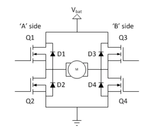
Image 1
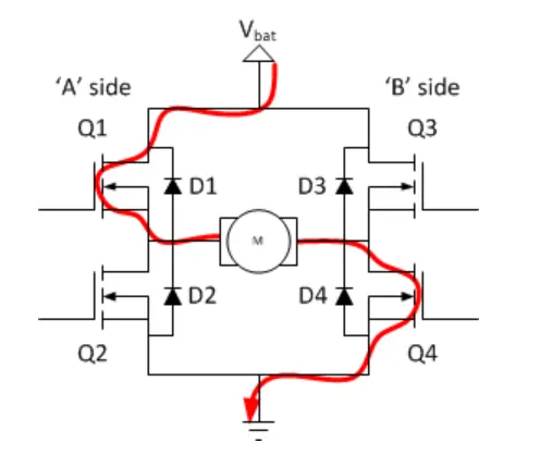
Image 2
when Q2 & Q3 switched ON ,a Negative voltage applied to the motor and diode D1-D4 operate as a freewheeling diodes when Q2 & Q3 are switch off.(ref. Image 3).
In a bridge, you should never ever close both Q1 and Q2 (or Q3 and Q4) at the same time. If you did that, you just have created a really low-resistance path between power and GND, effectively short-circuiting your power supply.
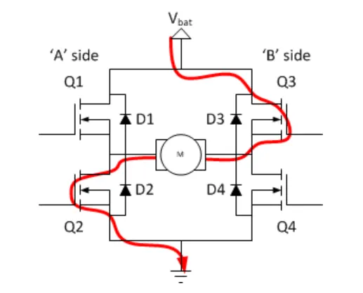
Image 3
Process:-
- Open the MATLAB & In the help documentation type DC MOTOR USING BJT-H Bridge.
- Result tab open then select the model and click open model.
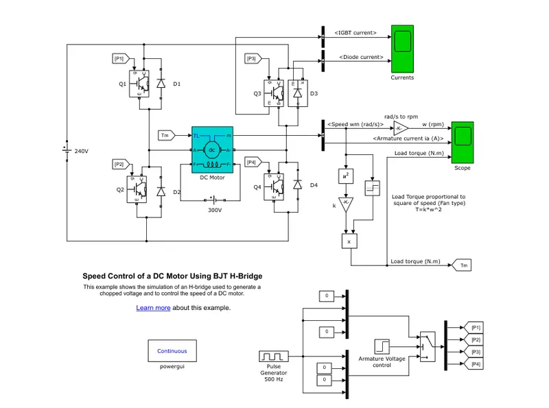
3. The model is opened in simulink workspace.
4. Run the model with default parameter & get the result.
5. change the parameter to the armature current does not shoot up when the motor changes direction of forword to reverse.
6. observed the result with default as well as changed parameter and comment on it.
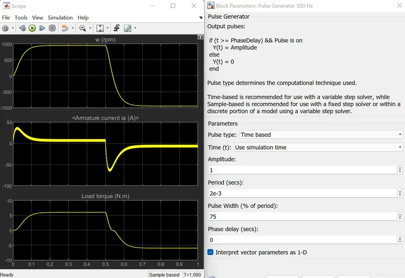
The result shows the speed of the motor,armature current,load torque with forword and reverse operating mode.as we see the current is starting of the operating mode that is forword and reverse operating mode current get to shootup and this current we have to reduce.
which can be done by reducing the firing angle of the transistor,so we have to reduce the parameter of the pulse generator,so we will decreases the pulse width by 50%.
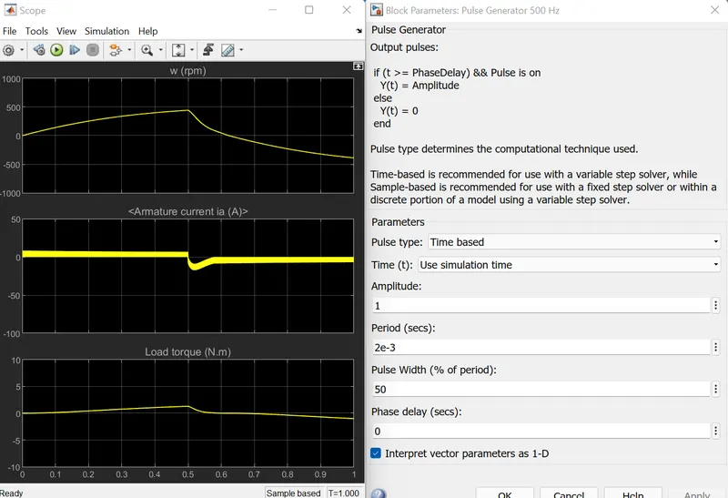
After changing parameter we can see at starting mode no shootup current.
C. Refer to the help section of ‘The Four-Quadrant Chopper DC Drive (DC7) block’. Compare it with the H-bridge model.
ANS:-
Compaire the DC7 and H-bridge
The Four-Quadrant Chopper,
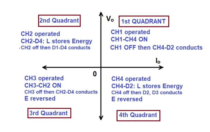
Type E or Four quadrant chopper consist of 4 semiconductor switches and 4 diodes are arrange in antiparallel.The 4 choppers are numbered according to which quadrant belong.their operation will be in each quadrant and the corrsponding chopper only be active in its quadrant.
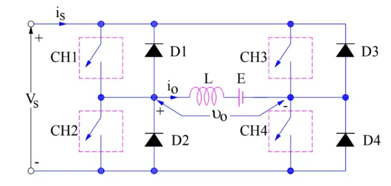
First Quadrant:-
During the first quadrant operation chopper CH1 & CH4 will be ON condition.voltage and current is positive.The load voltage Vo is equal to the source voltage Vs and load current io will begin to flow.Vo and io will positive in first quadrant operation. if we want to reduce or decreases the output voltage of the DC motor then CH1 will be turned OFF.the positive current feewheel through CH4 and diode D2.so in first quadrant forword motoring happens.
Second Quadrant:-
In this case CH2 will be turned ON and other 3 will be turned OFF.when voltage applied to the DC motor,EMF gets generated.current start flowing CH2-D4-L. energy store in the inductor (L). when CH2 wll be OFF then current fed back to the source through the diode D1 & D4. here (E+Ldi/dt) is more than the source voltage (Vs).it's called Forword braking the battery is charge from inductor stored energy.
Third Quadrant:-
In this quadrant the voltage & current both are negative. The CH2 & CH3 will be ON.for this quadrant working polarity should be zero.as the CH3 is ON,the load get connected to the Vs ,Vo and io will be negative in this mode. if we want to reduce or decreases the output voltage of the DC motor then CH3 will be turned OFF.the negative current feewheel through CH2 and diode D4.(CH2-D4-E-L), so in third quadrant Reverse motoring happens.
Forth Quadrant:-
In this case CH4 will be turned ON and other 3 will be turned OFF.when volage applied to the DC motor,EMF gets generated.current start flowing CH4-D2-E-L. energy store in the inductor (L). when CH4 wll be OFF then current fed back to the source through the diode D2 & D3. The operation will be in forth quadrant voltage is negative but load current is positive.it's called Reverse braking the battery is charge from inductor stored energy.
The Four-Quadrant Chopper DC Drive (DC7) block Model:-
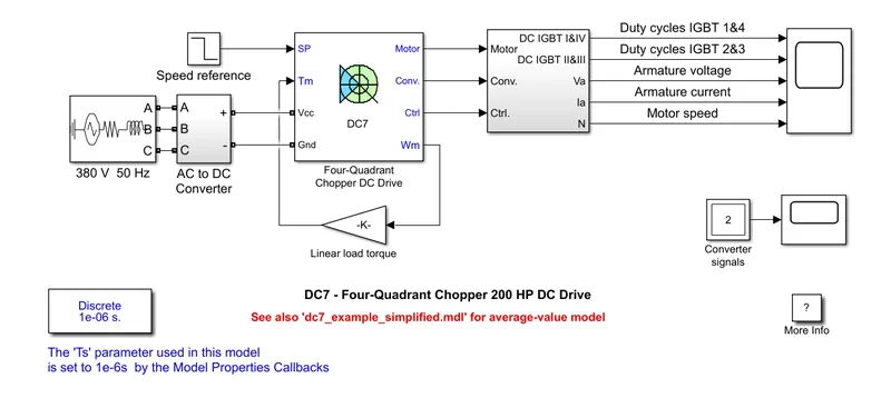
The 200HP DC motor separetely excited with constant 150V DC field voltage source. The armature voltage is provided by an IGBT converter controlled by 2 PI regulators. The converter is fed by a 515V DC bus obtained by rectification of a 380V 50Hz voltage source.In order to limit the DC bus voltage during dynamic braking mode the braking chopper has been added between diode rectifire and DC7 block.
The first regulator is a speed regulator,followed by current regulator.The speed regulator output the armature current reference used by current controller in order to obtain the electromagnetic torque needed to reach the desired speed.The speed referance change rate follows acceleration and deacceleration ramp in order to avoid sudden referance changes that could cause armature over current and destabilize the system.The current regulator controlled the armature current by computing the appropriate duty ratio of the 5khz pulses of the 4 IGBT devices .for proper system behaviour the instantaneous pulse value of IGBT devices 1 & 4 are opposite to 2 & 3.This generate the average armature voltage needed to obtained the desired armature current. In order to limit the amplitude of the current oscillation the smoothing inductance is placed in series with the armature circuit.
following result obtain after run this above model:-
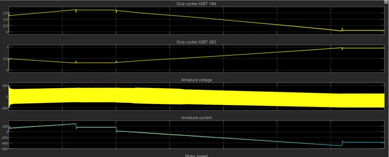
Comparision
- In 4 quadrant chopper DC drive operates in all 4 quadrant but in H bridge operation is only 2 quadrant.
- In 4 quadrant chopper DC drive operation which is Forword motoring,reverse motoring,forword braking,reverse braking and in H bridge operation only Forword and Reverse Motoring is their.
- In 4 quadrant chopper DC drive AC supply used and convert to DC with the help of rectifire but in H bridge Direct DC supply is used.
- In 4 quadrant chopper DC drive speed control is possible but in H bridge speed control is not possible.
- In 4 quadrant chopper DC drive given referance speed but in H bridge don't need referance speed.
- The stability of voltage and current supply is higher In 4 quadrant chopper DC drive as compaire to BJT as the 4 quadrat uss the step by step ramping startegy for change the motor direction wherever stability lost.
- In 4 quadrant chopper DC drive Regenerative braking is possible but in H bridge is not possible.
- The 4 quadrant chopper DC drive widely used in automobile sector to control DC motor speed and direction whereas BJT used in robotics and electromechanical devices to contol DC motor speed and direction.
- In 4 quadrant chopper DC drive the change the direction of the motor,current signal are interrupted whereas in H bridge polarity of current need to be changed.
- The 4 quadrant chopper DC drive provide better efficiency and operate high power level and H bridge operates at moderate power leves.
2. Develop a 2-quadrant chopper using simulink & explain the working of the same with the relevant results. (Refer to article - Multiquadrant operation of motor )
ANS:-
here I have made 2-quadrant chopper using simulink shown below,

- To start with the two-quadrant chopper drive,we have first given input from the DC source voltage. The voltage value kept to be 24V.
- For power switches or transistors,we will be using the MOSFET (metal oxide semiconductor field effect transistor) coupled with the Diodes in parallel.Their will be two pairs of these switches and diode so that we can operate the model in 2 quadrant and all this are connected accordingly.
- also i have used the NOT gate because to ensure that both the switches should not be connected simultaneously,if they do supply will be short circuited.
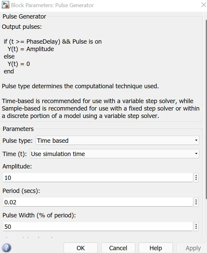
- Now, the pulse generator with 50% duty cycle,0.02sec and 10 as an amplitude.the output of pulse generator connected to the NOT gate.
- The inductor is provide the store the current when switch 1 is turned OFF.then for the load we have used another DC source with the voltage of 12V.
- To measure the voltage and current,the measuring block is used whose output can be visualized using the scope.
- we need the powergui block to simulate the any simulink model containing simscape Electrical specialized power system blocks.it stores the equivalent simulink circuit that represents the state-space equations of the model.
Working:-
- In a Two quadrant chopper,the average voltage will be always positive but the average load current might be positive or negative.The two switches CH1 AND CH2 should not be turned ON simultaneously as the combined action may cause a short circuit in supply lines.
- When chopper CH1 (MOSFET) is ON,the current flow from the source to load the inductore stores energy.The current flow from MOSFET 1 to the inductor to the load means the voltage and current are flowing from source to load.
- When CH1 turned OFF,the freewheeling diode start conducting and the output voltage will be equal to V.The direction of the load current will be reversed since the inductor is now discharging itself and current will be flowing towords the source.
- For the Regenerative braking the load current will be Negative when CH2 is ON.The current complete its path from the MOSFET 2 to the negative terminal of load diode to the diode 2.
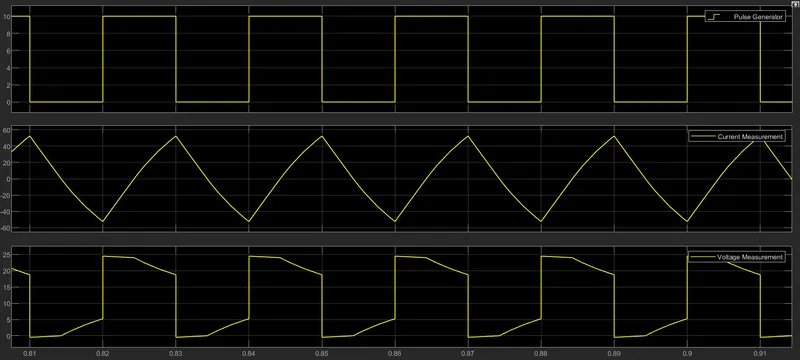
The output waveform as shown in below fig.(pulse generator,current measurment and voltage measurment)
3. Explain in a brief about operation of BLDC motor.
ANS:-
Brushless DC electric motor also known as electronically commutated motor.A brushless DC motor is a permanent magnet synchronous electric motor which is driven by direct current(DC). electrically and it electronically controlled commutation system.(commutation is process of producing rotational torque in the motor by changing the phase current through it appropriate times).BLDCmotor also referred as trapazoidal permanent magnet motor.
Unlike conventional brushed type DC motor,where in the brushes make the mechanical contact with commutator on the rotor so as to from an electric path between a DC electric source and rotor armature winding,BLDC motor employs electrical commutation with permanent magnet rotor and a stator with a sequence of coil.In this motor permanent magnet roates and current carrying condctor are fixed.
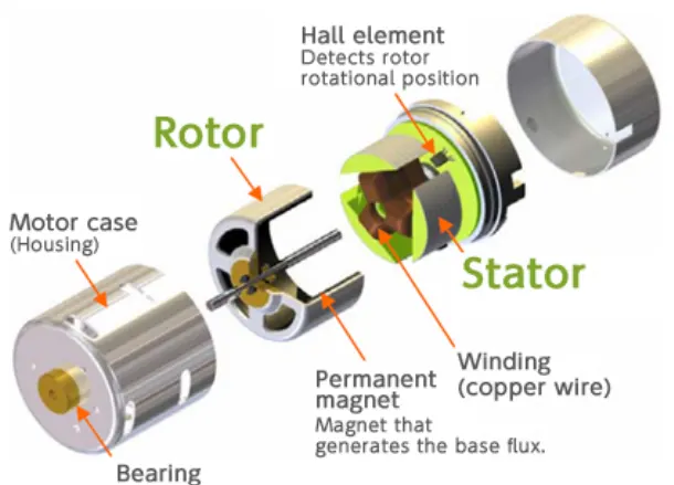
The armature coil are switched electronically by transistor or SCR at the correct rotor position in such a way that armature field is in space quadrature with the rotor field poles.hence the force acting on the rotor causes it to rotate.Hall sensors or rotary encoders are most commonly used to sense the position of the rotor and are position around the stator.the rotor position feedback from the sensor helps to determine when to switch thearmature current.
The electronic commutation arrangement eliminates the commutator arrangement and brushes in a DC motor and hence more reliable and less noisy operation is achived.
Due to absence of brushes BLDC motors are capable to run high speeds.The efficiency of BLDC motor is typically 85 to 90%,whereas as brushes type DC motor 75 to 80% efficient. Their are wide variations of BLDC motors available running from small power range to fractional horce power.
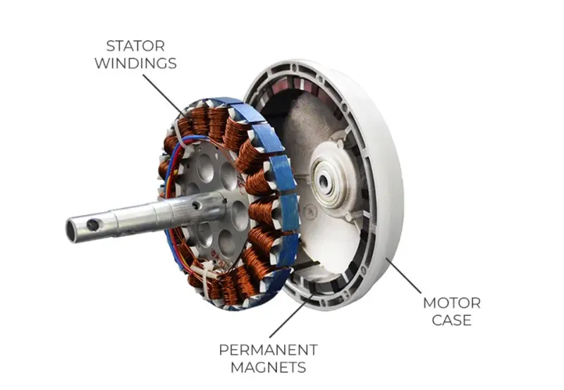
In this motor the permanent magnet attached to rotor.The current carrying conductor or armature winding are located on stator. They use electrical commutation to convert electrical energy into mechanical energy.
The main design difference between a brushes or brushless motor is replacement of mechanical commutator with an electrical switch circuit. A BLDC motor is a type of synchronous motor in the sense that the magnetic field generated by the stator and the rotor revolve at the same frequency.
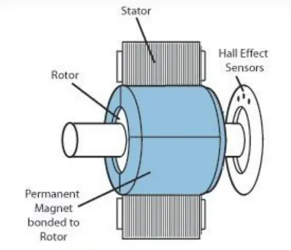
Brushless motor does not have any current carrying commutators.The field inside a brushless motor is switched through an amplifire which is triggered by the commutating device like an optical encoder.
BLDC motor can be constructed in different physical configurations.Depending on the stator windings,these can be configured as single phase ,two phase or three phase motors.however three phase BLDC motor with permanent magnet rotor are most commonly used.
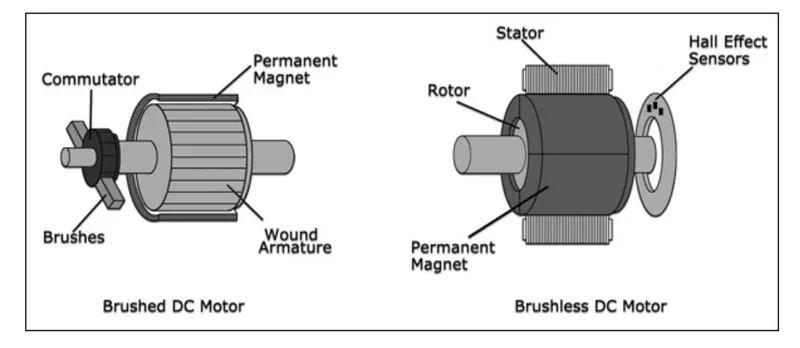
The construction of this motor has many similarities of three phase induction motor as well as conventional DC motor.This motor has ststor and rotor parts as like all other motors.as shown above fig.
STATOR
Stator of BLDC motor made up of stacked steel laminations to carry the windings.This windings are placed in slot which are axially cut along the inner periphery of the stator.this winding can be arrange in either star or delta.However most BLDC motor have three phase star connected stator.
each winding is constructed with numerous interconnected coils,where one or more coils are placed in each slot.In order to form an even number of poles,each of this winding distributed over the stator periphery.
The stator must be chosen with the correct rating of the voltage depending on power supply capability. For robotics ,automotive and small actuating applications,48V or less BLDC motor are preffered.
ROTOR
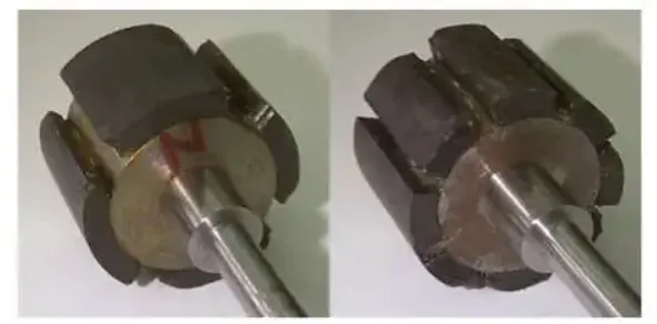
BLDC motor incorporates a permanent magnet in the rotor.The number of poles in the rotor can varry from 2 to 8 pole pairs with alternates north and south poles depending on the application requirment.In order to achive maximum torque in the motor,the flux density of the material should be high.a proper magnetic material for the rotor is needed to produce required magnetic field density.
HALL SENSORS
This sensor are uses in stator side. halll sensor provides the information to synchronous stator armature excitation with rotor position.since the commutation of BLDC motor is controlled ectronically. The stator winding should be energised in sequence in order to rotate motor. before energising the perticular stator winding, acknowledgment of rotor position is necessary.so the hall effect embedded in stator senses in rotor position.
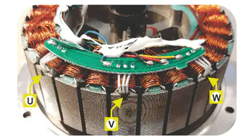
Most BLDC motor incorporate three sensors which are embedded into the stator as shown above fig.each sensor generate low and high signals wherever rotor poles pass near to it. The exact commutation sequence to the stator winding can be determined based on combination of these three sensor response.
WORKING PRINCIPLE:-
The underlying principles for the working of a BLDC motor are the same as for brushed DC motor.In BLDC motor it is achived using multiple feedback sensors.If the direction of the magnetic field is reverse ,the voltage developed will reverse as well.
Consider the following setup of three winding in stator designated A,B,and C.For the sake of understanding,let us replace the rotor with a single magnet.we know that when the current is applied through a coil,a magnetic field is generated and the orientation of the field lines i.e. the pole of the generated magnet will depend on direction of the current through winding.
Using this principle,if we supply current to the coil 'A' so that it will generate a magnetic field and attract rotor magnet.The position of rotor magnet will shift slightly clockwise and will align with 'A'.
If we now pass current through coil 'B' & 'C' one after the other(in that order),the rotor magnet will rotate in clockwise direction.
To increase the efficiency we can wind the opposite coil using a single coil so that we get double attraction.Further increasing the efficiency ,we can energize two coils at the same time so that one coil will attract the magnet and other coil will repel it.During this third will be ideal.
For a complete 360 degree rotation of the rotor magnet,six possible combination of the coils A,B and C are applicable.
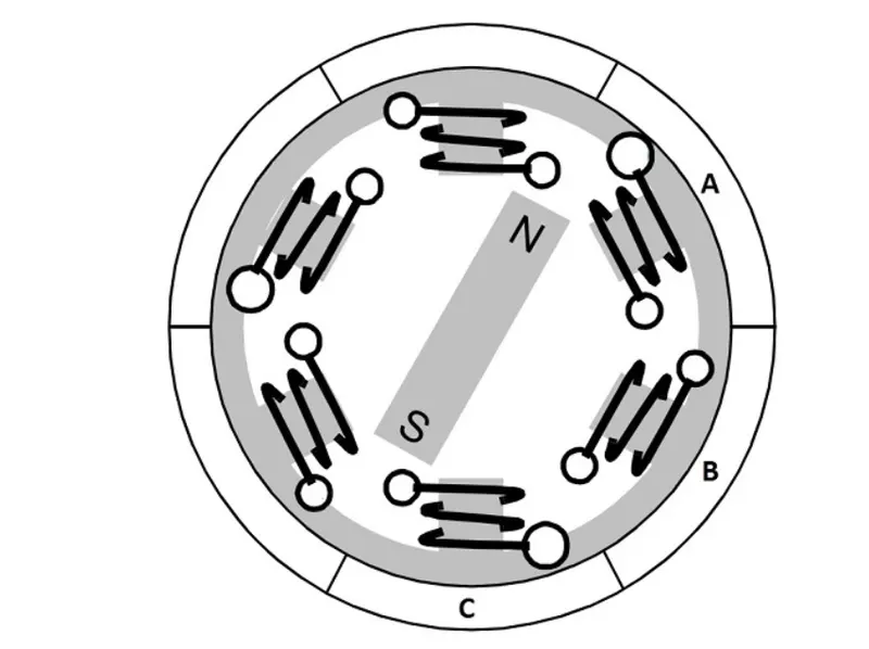
One phase is positive,one phase is negative and the third phase is idle.so based on the inputs from the Hall sensors,we have two switch the phases.
ADVANTAGES OF BLDC MOTOR:-
- Less overall maintenance due to absence of brushes.
- Higher speed range and lower electric noise generation.
- It has no mechanical commutator and associated problem.
- High efficiency and high output power.
- high speed of operation even in loaded or unloaded due to absence of brushes that limit the speed.
- long lifeas no maintenance is required for commutation system.
DISADVANTAGES OF BLDC MOTOR:-
- These motor are costly.
- Electronic controller required to control this motor is expensive.
- Need of additional sensor.