Week-7 Challenge: DC Motor Control
Ans 1A: H- Bridge Circuit
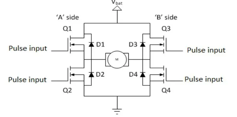
A H-bridge Circuit is a simple four q Circuit, where the input is provided as Vbat.
Here the motor is connected in the center of the circuit, which looks like the letter H.
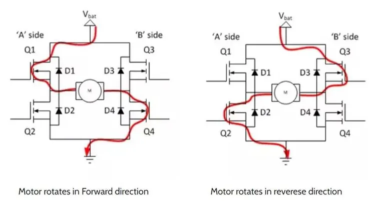
The direction of current flow is shown in the following dia.
- In positive half cycle switches Q1 and Q4 conducts and motor rotates in forward direction. The diode D1 & D4 are in turn off condition.
- In negative half cycle switches Q2 and Q3 conducts and motor rotates in backward direction. The diode D2 & D3 are now in turn off condition.
- The Switches if not operated in a particular manner, it willl create low resistance path and somehow result in the Short-circuit.
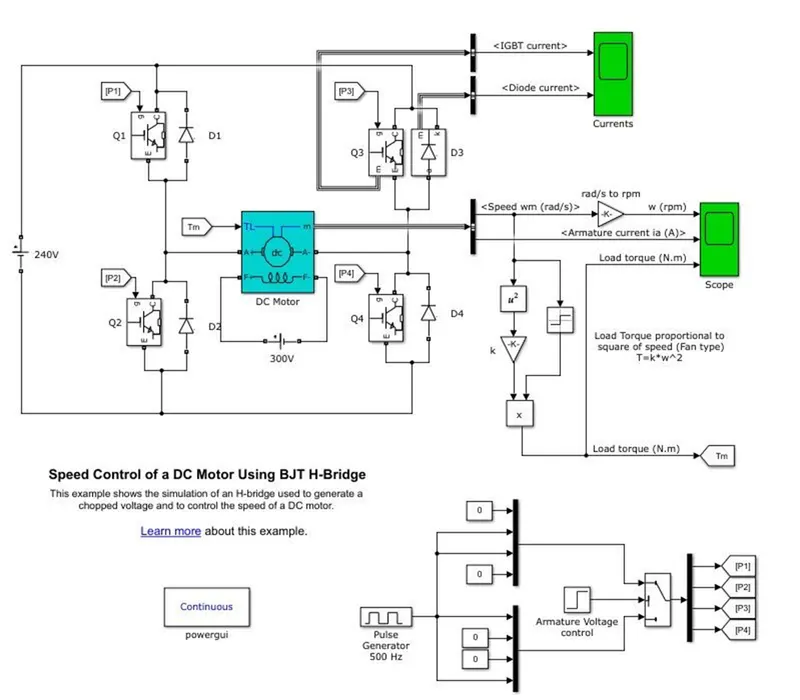
Simulink model of Speed control of a DC motor using BJT H-bridge
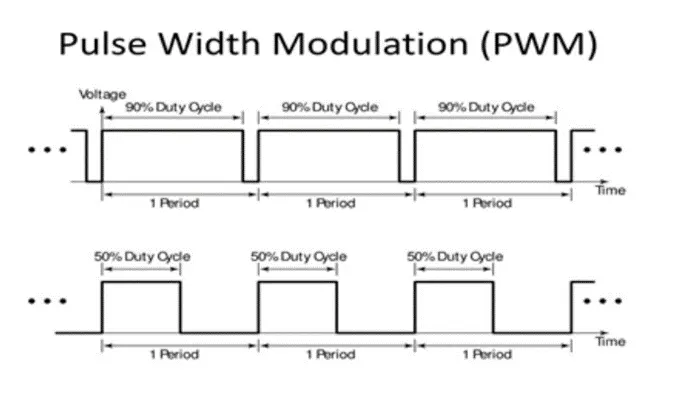
Pulse Width Modulation
Pulse-width modulation (PWM) is a powerful technique for controlling analog circuit with digital outputs. PWM is used in many applications, ranging from communications to power control and conversion. For example, the PWM is commonly used to control the speed of electric motors, the brightness of lights,and many more. In this module 75% Pulse width taken and time period is 2e-3sec.
Output Result of current
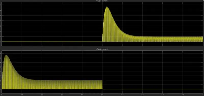
The waveform shows that 0 to 0.5 sec IGBT current are zero and diode current is occurred that means IGBT off and Diode is on conditions. After 0.5 to 1sec diode current are zero and IGBT current is occur that means diode off and IGBT is on conditions.
Output waveform of armature current, speed and load torque
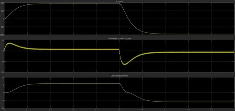
- From the waveform speed is start from zero & reaches up to max. speed 1000RPM and after 0.5sec it will decrease to -1000RPM
- The armature current rise at 40 to 45A & decreases immediately to reach zero. After 0.5sec it will go to negative near to zero
- The load torque follows the speed waveform in positive as well as negative direction
Ans B. Comment on the armature current shoot-up from the scope results.
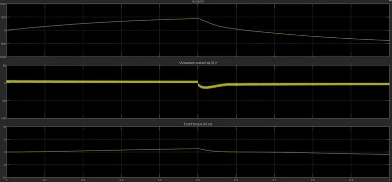
We have noticed that at the time of starting armature current a spike in the current flow and also in the negative directions of the current flow. If we want to reduce sudden rise in armature current waveform, we have to reduce duty cycle 75% to 50% and see result as shown in following results
Ans C. Refer to the help section of ‘The Four-Quadrant Chopper DC Drive (DC7) block’. Compare it with the H-bridge model.
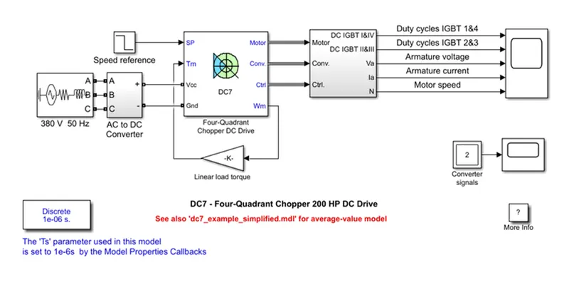
Comparison H-bridge and Four Quadrant chopper
|
Sr. No. |
H-bridge Model |
Four Quadrant chopper |
|
1 |
Can operate only in two modes i.e., forward and reverse mode |
Motor can operate in all four quadrants i.e., forward motoring, reverse motoring, forward braking and reverse braking |
|
2 |
Vehicle control is less as compare to Four quadrant chopper |
Sophisticated control vehicle using Four quadrant chopper |
|
3 |
Regenerative braking not possible |
Regenerative braking possible |
|
4 |
Signal are continuous |
Signal are discrete |
|
5 |
Used in Robotics |
Used in power control and signal application. |
Ans 2: There are two types of 2-quadrant chopper:
- Type A Chopper (Class C chopper)
- Type B Chopper (Class D chopper)
Class D Chopper
Class-D or Type-D chopper is a circuit configuration of chopper in which power can flow in either direction i.e., from source to load and load to source. The operation of this chopper is confined in first and fourth quadrant. This type of chopper is also known as Two quadrant Type-B Chopper. The necessary condition for this chopper is that load should be inductive.
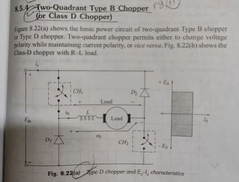
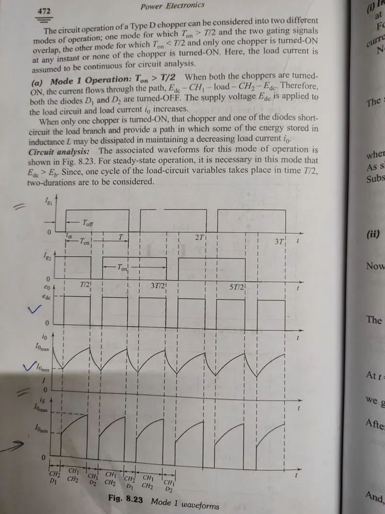
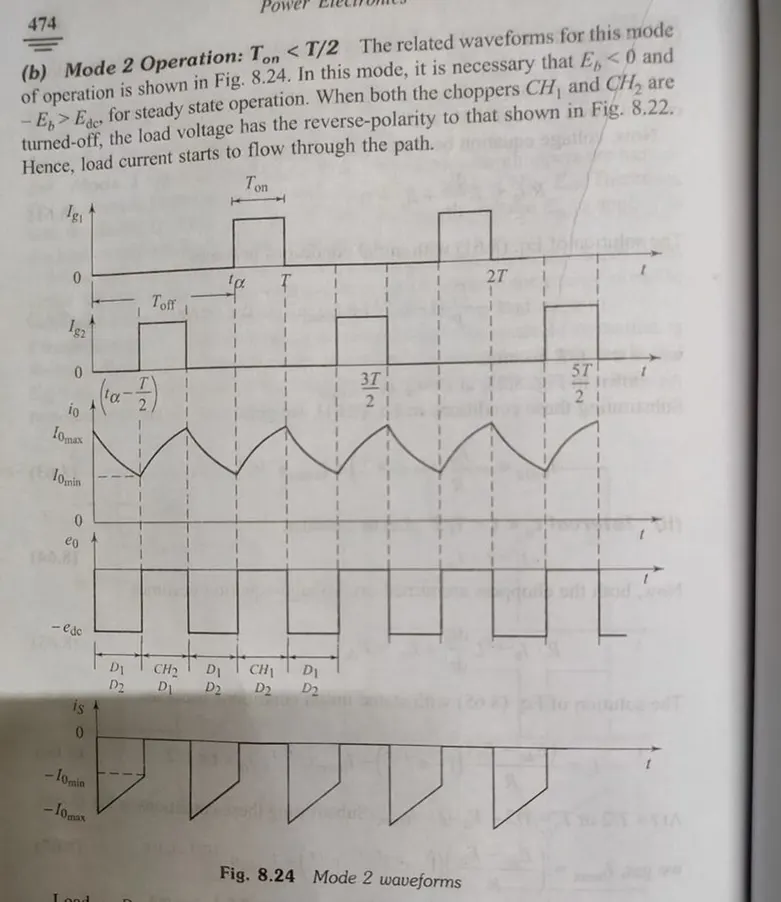
Simulink Model of 2-quadrant chopper
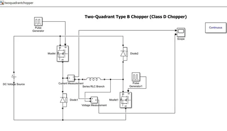
Taken Values: The inductor load L = 10e-3
DC Voltage Source = 12V
Amplitude = 10
Time Period = 0.02sec
Pulse width = 50%
Phase delay = 0
Run the model for 1Sec
Output Results
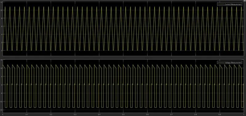
The output waveform of current is in positive direction and the voltage waveform in both positive as well negative directions occurs.
Reference Book: Power Electronics by K.B. Khanchandani
Q3. Explain in a brief about operation of BLDC motor.
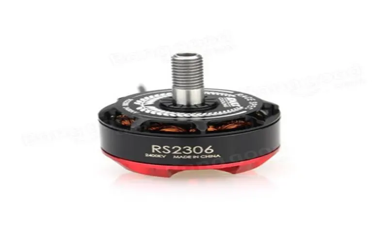
Ans 3: A brushless DC motor is an electronically commuted DC motor which does not have brushes. The controller provides pulses of current to the motor windings which control the speed and torque of the synchronous motor.
These types of motors are highly efficient in producing a large amount of torque over a vast speed range. In brushless motors, permanent magnets rotate around a fixed armature and overcome the problem of connecting current to the armature. Commutation with electronics has a large scope of capabilities and flexibility. They are known for smooth operation and holding torque when stationary.
Function:
Before explaining the working of a brushless DC motor, it is better to understand the function of a brushed motor. In brushes motors, there are permanent magnets on the outside and a spinning armature which contains electromagnet is inside. These electromagnets create a magnetic field in the armature when the power is switched on and help to rotate the armature.
The brushes change the polarity of the pole to keep the rotation on of the armature. The basic working principle for the brushed DC motor and for brushless DC motor are same i.e., internal shaft position feedback.
Brushless DC motor has only two basic parts: rotor and the stator. The rotor is the rotating part and has rotor magnets whereas stator is the stationary part and contains stator windings. In BLDC permanent magnets are attached in the rotor and move the electromagnets to the stator. The high-power transistors are used to activate electromagnets for the shaft turns. The controller performs power distribution by using a solid-state circuit.
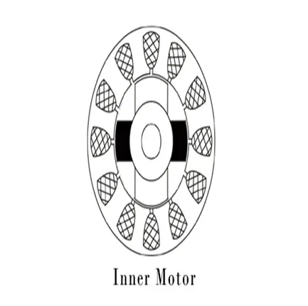
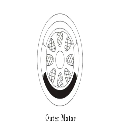
Basically, BLDC are of two types, one is outer rotor motor and other is inner rotor motor. The basic difference between the two is only in designing, their working principles are same.
Inner Rotor Design
In an inner rotor design, the rotor is located in the centre of the motor and the stator winding surround the rotor. As the rotor is located in the core, rotor magnets do not insulate heat inside and heat get dissipated easily. Due to this reason, inner rotor designed motor produces a large amount of torque and validly used.
Outer Rotor Design
In outer rotor design, the rotor surrounds the winding which is located in the core of the motor. The magnets in the rotor trap the heat of the motor inside and do not allow to dissipate from the motor. Such type of designed motor operates at lower rated current and has low cogging torque.
Working Principle:
BLDC motor works on the principle similar to that of a Brushed DC motor. The Lorentz force law which states that whenever a current carrying conductor placed in a magnetic field it experiences a force. As a consequence of reaction force, the magnet will experience an equal and opposite force. In the BLDC motor, the current carrying conductor is stationary and the permanent magnet is moving.
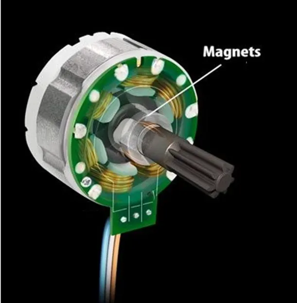
When the stator coils get a supply from source, it becomes electromagnet and starts producing the uniform field in the air gap. Though the source of supply is DC, switching makes to generate an AC voltage waveform with trapezoidal shape. Due to the force of interaction between electromagnet stator and permanent magnet rotor, the rotor continues to rotate.
With the switching of windings as High and Low signals, corresponding winding energized as North and South poles. The permanent magnet rotor with North and South poles aligns with stator poles which causes the motor to rotate.
Advantages of Brushless DC Motor
The advantages of a BLDC motor are:
- Brushless motors are more efficient as its velocity is determined by the frequency at which current is supplied, not the voltage.
- As brushes are absent, the mechanical energy loss due to friction is less which enhanced efficiency.
- BLDC motor can operate at high-speed under any condition.
- There is no sparking and much less noise during operation.
- More electromagnets could be used on the stator for more precise control.
- BLDC motors accelerate and decelerate easily as they are having low rotor inertia.
- It is high performance motor that provides large torque per cubic inch over a vast sped rang.
- BLDC motors do not have brushes which make it more reliable, high life expectancies, and maintenance free operation.
- There are no ionizing sparks from the commutator, and electromagnetic interference is also gotten reduced.
- Such motors cooled by conduction and no air flow are required for inside cooling.
Limitations of Brushless DC motor
- These motors are costly
- Electronic controller required control this motor is expensive
- Requires complex drive circuitry
- Need of additional sensors
Applications of Brushless DC motor
Brushless DC motors (BLDC) use for a wide variety of application requirements such as varying loads, constant loads and positioning applications in the fields of industrial control, automotive, aviation, automation systems, health care equipment’s etc.
- Computer hard drives and DVD/CD players
- Electric vehicles, hybrid vehicles, and electric bicycles
- Industrial robots, CNC machine tools, and simple belt driven systems
- Washing machines, compressors and dryers
- Fans, pumps and blowers.