Week-7 Challenge: DC Motor Control
CHALLENGE 7
ANSWER 1 :
SPEED CONTROL OF DC MOTOR USING BJT H-BRIDGE.
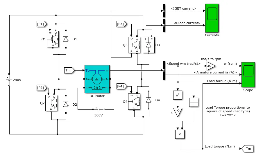
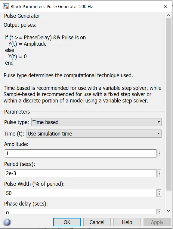
The inbuilt model and pulse generator is as below :
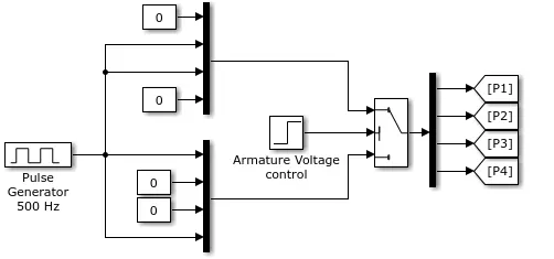
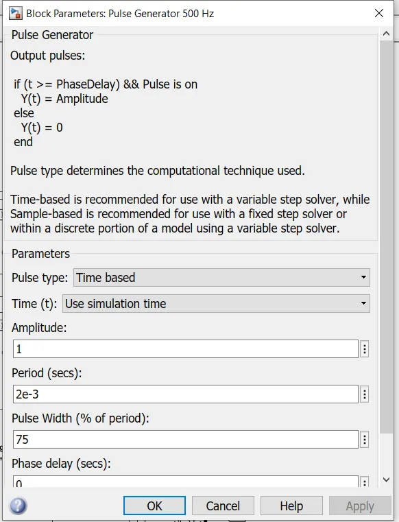
The pulse generator inputs are as follows :
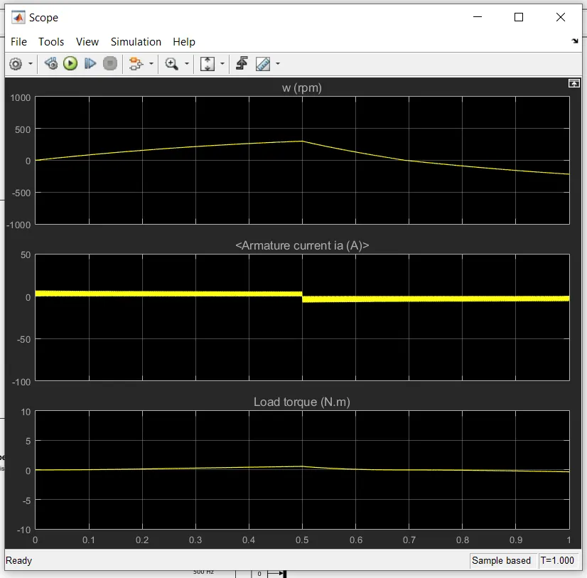
Now, if we run the model we can get the results or the behaviour of the voltages and currents as follows :
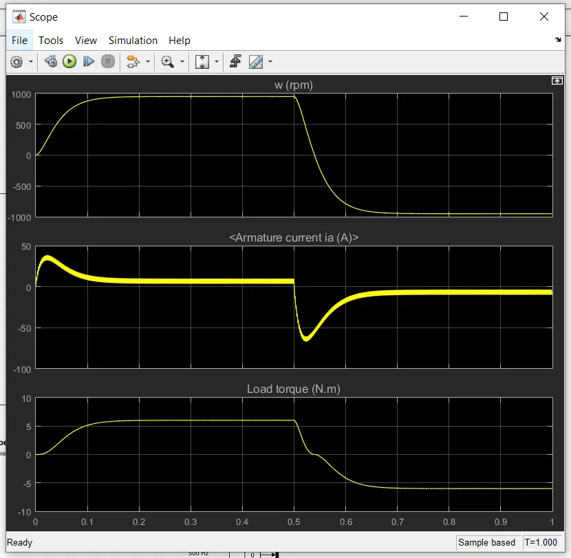
So, we can observe the armature current shoot-up at the beginning of the cycle, which is due to the starting power required to start and accelerate the vehicle.
As the required acceleration and speed is obtained, the armature current is reduced and maintained nearly constant.
Again, when the motor runs in the opposite direction, the motor requires power to oppose the current speed plus it should have the power to accelerate in the opposite direction as well, which is the reason for the higher negative shoot up in the armature current.
So, we are going to try and reduce this shoot up as effective as possible.
Now if we reduce the duty cycle to 60% the shoot ups are reduced significantly.
And when the duty cycle is reduced to 50% the shoot up is almost disappeared.
So, the stats with 50% duty cycle with almost no shoot ups in armature current is given below :
ANSWER 2 :
Difference between BJT H-bridge model and DC7 model :
BJT H-BRIDGE MODEL.
The whole H-bridge circuit is designed only with 4 IGBT and diodes which operates and acts as input signals to control the DC machine.
And the required signals are generated using a pulse generator.
So, the design is more simple and takes very less time to simulate.
Here, the torque is proportional to the square of speed.
DC7 MODEL.
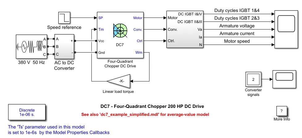
Here, the entire circuit is all put together in a single Simulink block with braking chopper used for regenerative braking and the inputs given are speed and torque, with which the DC7 model decides the switching operations required and simulation is done accordingly.
The armature voltage is controlled by using PI controllers.
Most of all here the current overshoot is also reduced to the optimum level with the help of smoothing inductance placed in series with the armature circuit.
Here, the torque is directly proportional to speed, that is linear load torque.
ANSWER 3 :
The DC7 drive model is as below:
And the output of the simulation of the inbuilt DC7 block with 150V field DC source and linear load torque is as follows :
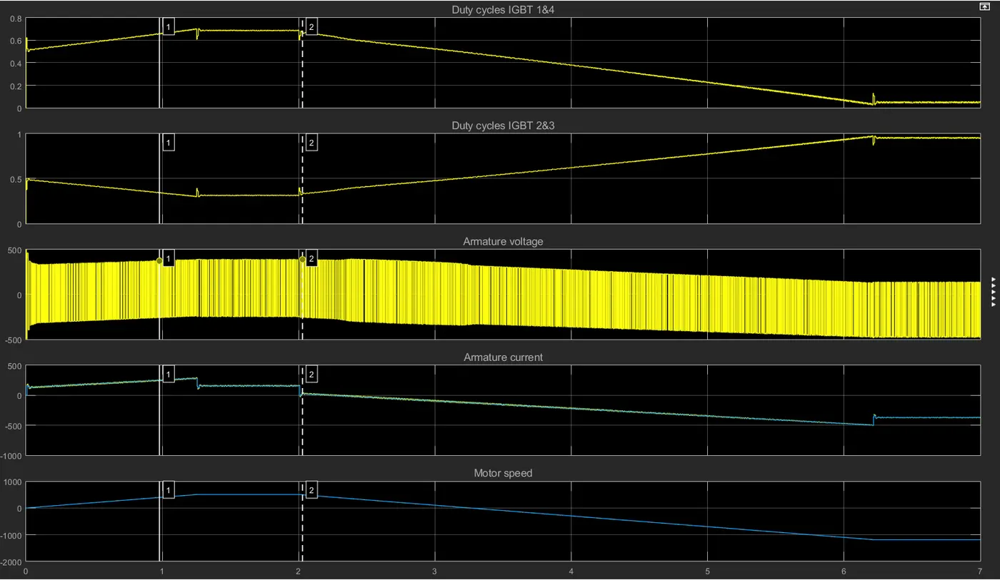
Now, we are going to create a Electric vehicle model using DC7 model with slight changes as mentioned below :
Instead of linear torque, we are going to provide the following equation for torque input :
T = 24.7 + 0.0051w2.
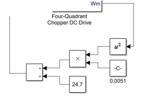
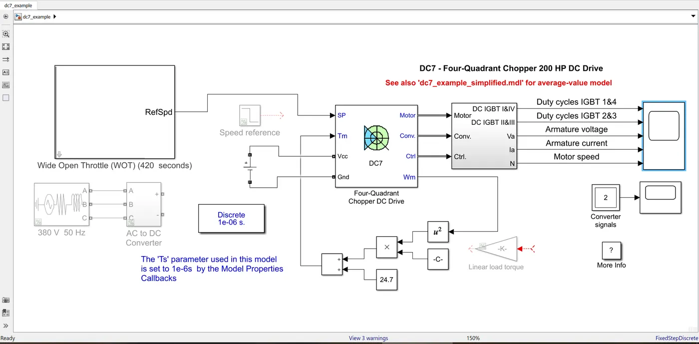
Also, the voltage supply is directly given from a DC source.
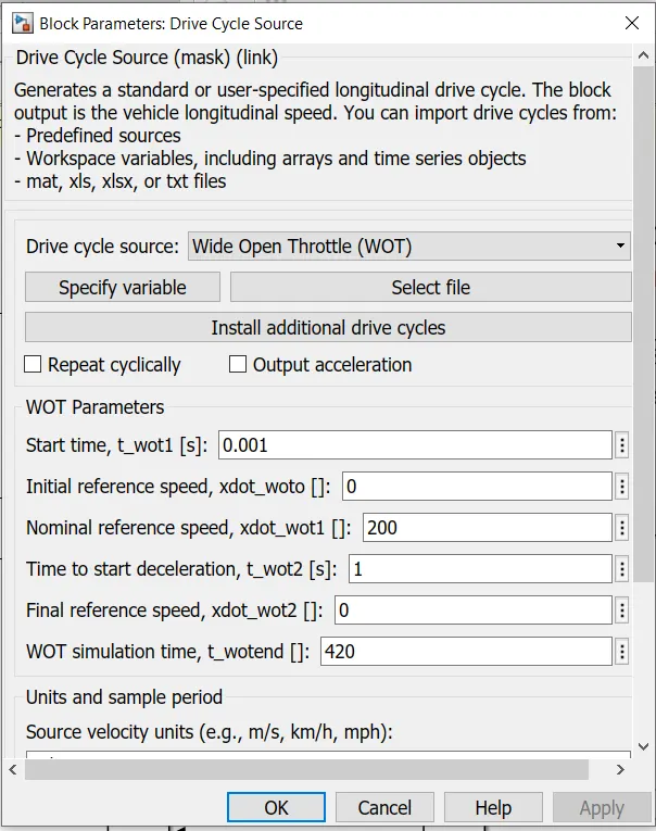
The wide open throttle reference speed is given as input.
The modified DC7 model for EV simulation is as follows :
So, we can also clearly see the modifications made to the model.
Now, as we simulate the model we get the following results in the scope.
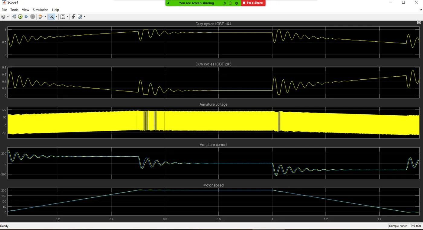
As the simulation runs,
While starting the model draws more current for acceleration.
And as the required speed is obtained the current required is also reduced.
Also after certain time when the motor has to decelerate the current required is also negative, that is in the opposite direction until the motor has come to rest or has to accelerate again.