Week-7 Challenge: DC Motor Control
1. A. Explain a MATLAB demo model named ‘Speed control of a DC motor using BJT H-bridge.
A H-bridge is an electronic circuit that switches the polarity of a voltage applied to a load. These circuits are often used in EV , HEV, robotic and and other applications to allow DC motors to run forwards or backwards Most DC-to-AC converters, DC-to-DC, motor controllers and many other kinds of power electronics the H bridges.. The name is derived from its common schematic diagram representation, with four switching elements configured as the branches of a letter "H" and the load connected as the cross-bar. The bollow diagram is a BJTH H bridge model used to contorl the speed of a DC motor.
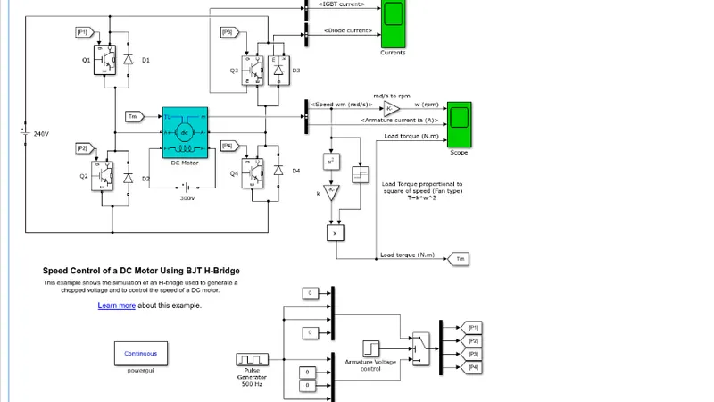
-An H-bidge is generaly circuit containing four switching elements and the load at the center.
-In the above circuit we have four switching elements (Q1...Q4) which are basicaly Bipolar Junction Transistors (BJT).
-Each having a diode (D1...D4) respectively which are called catch diodes.
-Each switching transistor is conected to a Puls generator (P1..P4) respectively to control the on and off switching of the transistors.
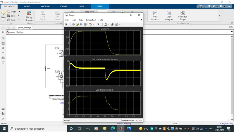
-2 Scops are connected to give out the following outputs. Scope1 gives a plot of IGBT current and Diode current while scope2 gives a plot of speed in rpm, Armature current and load torge.
-The model principarly works in 4 Quadrants.
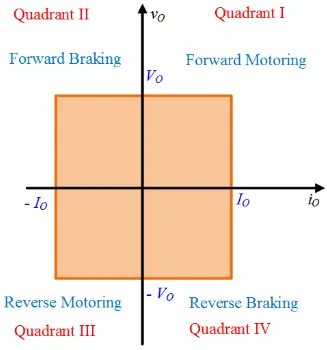
Quadrant 1: In this quadrant Q1 and Q4 are turned on or closed. current flows in positive direction from Q1 over the motor load then to Q4 and back to negative surply. Curren and voltage are positve (Speed and Torgue are positive) Hence Forward Motoring. when Q1 is opened, the diode D2 becomes forward biased. Curren stored in inductor flows through Q4 nad D2 in a closed circuit.
Quadrant 2: In this quadrant Q2 is turned on. current flows from the 300v motor back emf through Q2 in through forward biased D4 back to motor 300v surply.In this Quadrant Voltage remains positive (Speed remains positive). When Q2 is turned off D1 becomes forward biased. hence current flows from 300v positive terminals through D1 then through 240v surply, through D4 and back to 300v negative surply. Hence the current is negative in second quadrant(torgue is negative). This is also called Forward braking (Regeneration process).
Quadrant 3: In this quadrant Q3 and Q2 are turned on. current flows in positive direction from Q3 over the motor load then to Q2 and back to negative terminal surply. Curren move in negative direction over the motor. Here we clearly see that the voltage is negative polarity. Hence Current and voltage are negative in this quadrant (Speed and Torgue are negative). When Q3 is turned off, energy stored in inductor passes through Q2 and D4.
Quadrant 4: In this quadrant only Q4 is turned on. The 300v of motor back emf has a reversed polarity.Current flows in reversed direction through Q4 through D2 and back to surply. Voltage polarity here is negative but current flows in positive direction over the motor. Back emf generates ernegy which is stored by the inductor. This is a regenrative mode. This is also known as reverse braking (Speed is nagative but torgue is positive).
Simulation Results
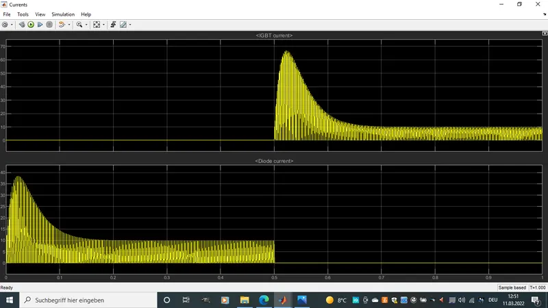
-Here we see that Q3 and D3 never opperate at the same time
-We observe that the motor slows down when current polatity is changed. The motors then works as a generator till it enters the revers mode where rotation is in the negative direction.
B. Comment on the armature current shoot-up from the scope results.
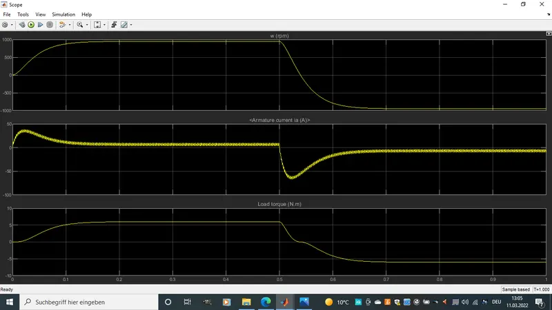
- From the Armature current we observes the different times when current enters the various phases. At the beginning the current is in the first quadrant where it is positive. After 0.5 sec its in the second quadrant and third quadrant.Then after it starts moving to the 4 Quadrant.
-The duration of ripple depends on the choosen duty cycle hence the duration at which current moves in a particular transistor.
C. Refer to the help section of ‘The Four-Quadrant Chopper DC Drive (DC7) block’. Compare it with the H-bridge model.
The Four-Quadrant Chopper DC Drive (DC7) block
The Four-Quadrant Chopper DC Drive (DC7) block represents a four-quadrant, DC-supplied, chopper (or DC-DC PWM converter) drive for DC motors. This drive features closed-loop speed contol with four quadrant operation.The speed contol outputs the reference armature current of a machine. Using a PI current controller, the chopper duty cycle corresponding to the commanded armature current is derived. This duty cycle is then compared with a sawtooth carrier signal to obtain the required PWM signals for the chopper.
- The main advantage of this drive, compared with other DC drive, is that it can operate in all four quadrant (forward motoring, reverse regeneration, reverse motoring, and forward regenerating). In addition, due to the use of high switching fraquency DC-DC converters, a lower armature current ripple (compared with thyristor-based DC drives) is obtained. However, four switching devices are required which increase thecomplexity of the drive system.
-The machine is separately excited with a constant DC field voltage source. There is thus no field voltage control. By default, the field current is set to its steady-state value when a simulation is started.
-The armature voltage is provided by an IGBT converter controlled by two PI regulators. The converter is fed by a constant DC voltage source. Armature current oscillations are reduced by a smoothing inductance connected in series with the armature circuit.
H-bridge model.
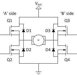
Working principle
Quadrant 1: In this quadrant Q1 and Q4 are turned on or closed. current flows in positive direction from Q1 over the motor load then to Q4 and back to negative surpply. Curren and voltage are positve (Speed and Torgue are positive) Hence Forward Motoring. when Q1 is opened, the diode D2 becomes forward biased. Curren stored in inductor flows through Q4 nad D2 in a closed circuit.
Quadrant 2: In this quadrant Q2 is turned on. Motor back emf flows through Q2 in through forward biased D4 back to motor surpply.In this Quadrant Voltage remains positive (Speed remains positive). When Q2 is turned off D1 becomes forward biased. hence current flows from motor positive terminals through D1 then through 240v surply, through D4 and back to mootr negative surpply. Hence the current is negative in second quadrant(torgue is negative). This is also called Forward braking (Regeneration process).
Quadrant 3: In this quadrant Q3 and Q2 are turned on. current flows in positive direction from Q3 over the motor load then to Q2 and back to negative terminal surpply. Curren move in negative direction over the motor. Here we clearly see that the voltage is negative polarity. Hence Current and voltage are negative in this quadrant (Speed and Torgue are negative). When Q3 is turned off, energy stored in inductor passes through Q2 and D4.
Quadrant 4: In this quadrant only Q4 is turned on. The motor back emf has a reversed polarity.Current flows in reversed direction through Q4 through D2 and back to surply. Voltage polarity here is negative but current flows in positive direction over the motor. Back emf generates ernegy which is stored by the inductor. This is a regenrative mode. This is also known as reverse braking (Speed is nagative but torgue is positive).
2. Develop a 2-quadrant chopper using simulink & explain the working of the same with the relevant results. (Refer to article - Multiquadrant operation of motor )
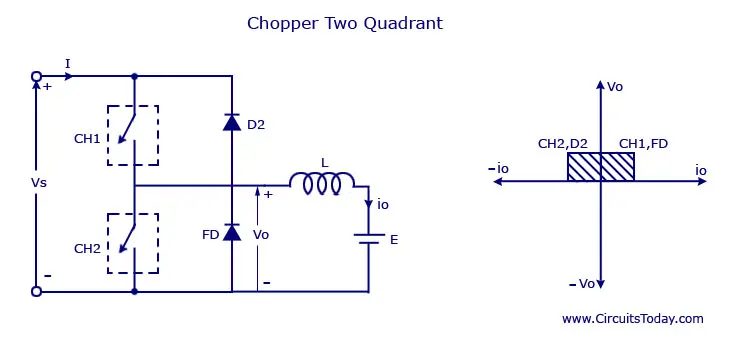
Description:
CH = Chopper switch
D2 = Diode
FD = Free wheeling diode
- Vo is called output voltage and it is always possitive due to the free-wheeling diode.
-When switch CH2 is on or FD conducts, then the output voltage Vo = 0
-When switch CH1 is on, D2 conducts, and the output voltage Vo = Ve and current Io changes to reverse direction
-CH1 and CH2 should never be operated simultaniously, cause this will cause a short circuit
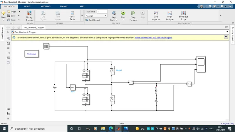
-In the below model mosfet where used as switching elements. A puls modulator with a not block to simultanously open and close both mosfets so that they never at the same time fine them selves in open or close position.
-Current and Voltage are measured at appropriate terminals and given out to the scope for lataer analizing.
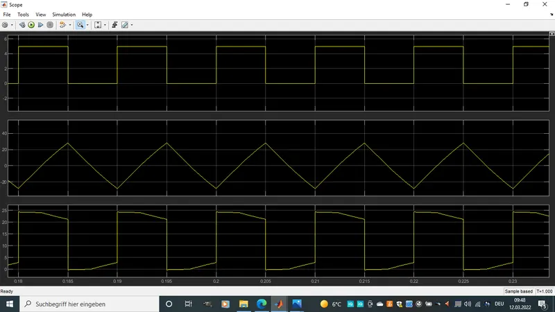
-The first graph shows the puls modulator switching on and off both mosfet. when puls is at 5 mosfet 1 is on, when puls is at 0 mosfet 1 is off and musfet 2 is on.
-The second is current flow across the load. we see that when mosfet 1 is on current flows in positive direction while when mosfet 2 is on current flows in negative direction across the load.
-The inductor charges up when current flows across and empties itself when mosfet is off and charges the voltage supplier.
-The 3 graph shows the voltage plot, the voltage is always positive regardless of the which direction the current flow. it drops down to 0 but never gose to negative direction.
3. Explain in a brief about operation of BLDC motor.
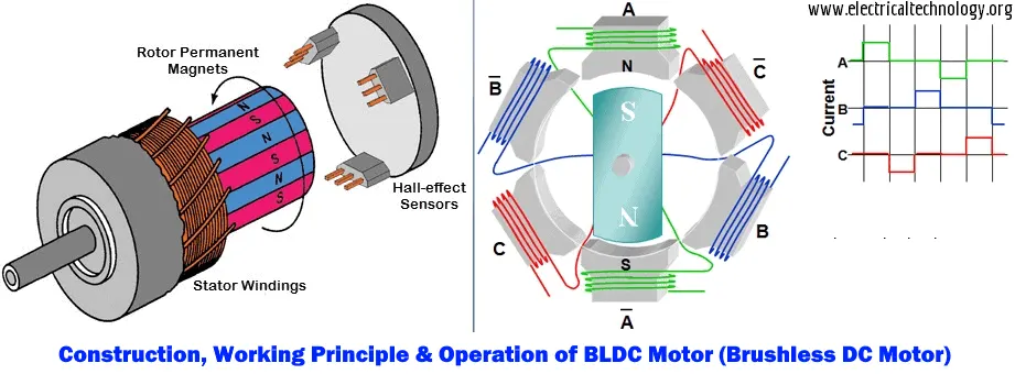
- A brushless DC motor (also known as a BLDC motor or BL motor) is an electronically commuted DC motor which does not have brushes.AIt is a rotating electric machine, where the stator is a classic 3-phase stator like that of an induction motor, and the rotor has surface-mounted permanent magnets. Most BLDC motors use three Hall sensors that feedback the rotor position every 60°. BLDC motor works on the principle similar to that of a conventional DC motor, i.e., the Lorentz force law which states that whenever a current carrying conductor placed in a magnetic field it experiences a force. As a consequence of reaction force, the magnet will experience an equal and opposite force. A BLDC motor can be controlled with the help of Hall sensors and a power electronic system. Hall sensors detect the rotor position and generate a high or low signal according to the position of the ro tor.
-The controller provides pulses of current to the motor windings which control the speed and torque of the synchronous motor. A Brushless DC Electric Motor (BLDC) is an electric motor powered by a direct current voltage supply and commutated electronically instead of by brushes like in conventional DC motors.
- BLDC motors have traction characteristics like high starting torque, high efficiency around 95-98%, etc. BLDC motors are suitable for high power density design approach. The most common uses of brushless DC motors in industrial engineering appart bean used for EV or HEV are linear motors, servomotors, actuators for industrial robots, extruder drive motors and feed drives for CNC machine tools.They have many advantages like low cost, simplicity, reliability, good performance, long life.