Week-7 Challenge: DC Motor Control
1. A. Explain a MATLAB demo model named ‘Speed control of a DC motor using BJT H-bridge’.
B. Comment on the armature current shoot-up from the scope results.
C. Refer to the help section of ‘The Four-Quadrant Chopper DC Drive (DC7) block’. Compare it with the H-bridge model
ANSWER:
Speed Control of a DC Motor Using BJT H-Bridge
This example shows the simulation of an H-bridge used to generate a chopped voltage and to control the speed of a DC motor.Gilbert Sybille (Hydro-Quebec
The Bipolar Junction Transistor (BJT) when used for power switching applications, operates as an IGBT. When it is conducting (BJT operating in the saturated region), a forward voltage Vf is developed between collector and emitter (in the range of 1 V). Therefore, the IGBT block can be used to model the BJT device.
The IGBT block does not simulate the gate current controlling the BJT or IGBT. The switch is controlled by a Simulink® signal (1/0). The DC motor uses the preset model (5 HP 24V 1750 rpm). It simulates a fan type load (where Load torque is proportional to square of speed). The armature mean voltage can be varied from 0 to 240 V when the duty cycle (specified in the Pulse Generator block) is varied from 0 to 100%.
The H-bridge consists of four BJT/Diode pairs (BJT simulated by IGBT models). Two transistors are switched simultaneously: Q1 and Q4 or Q2 and Q3. When Q1 and Q4 are fired, a positive voltage is applied to the motor and diodes D2-D3 operate as free-wheeling diodes when Q1 and Q4 are switched off. When Q2 and Q3 are fired, a negative voltage is applied to the motor and diodes D1-D4 operate as free-wheeling diodes when Q2 and Q3 are switched off.
Simulation
The motor starts in the positive direction with a duty cycle of 75% (mean DC voltage of 180V). At t= 0.5 sec., the armature voltage is suddenly reversed and the motor runs in the negative direction.
'Scope' shows motor speed, armature current and load torque and 'Currents' shows currents flowing in BJT Q3 and diode D3.
2. Develop a 2-quadrant chopper using simulink & explain the working of the same with the relevant results. (Refer to article - Multiquadrant operation of motor )
ANSWER:
For consideration of multi quadrant operation of drives, it is useful to establish suitable conventions about the signs of torque and speed.
A motor operates in two modes – Motoring and braking. In motoring, it converts electrical energy into mechanical energy, which supports its motion .In braking it works as a generator converting mechanical energy into electrical energy and thus opposes the motion.
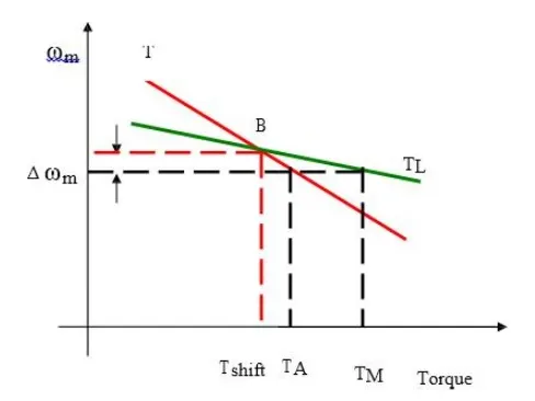
Now consider equilibrium point B which is obtained when the same motor drives another load as shown in the figure. A decrease in speed causes the load torque to become greater than the motor torque, electric drive decelerates and operating point moves away from point B.
Similarly when working at point B and increase in speed will make motor torque greater than the load torque, which will move the operating point away from point B
Similarly operation in quadrant III and IV can be identified as reverse motoring and reverse braking since speed in these quadrants is negative.
For better understanding of the above notations, let us consider operation of hoist in four quadrants as shown in the figure. Direction of motor and load torques and direction of speed are marked by arrows
The figure at the right represents a DC motor attached to an inertial load. Motor can provide motoring and braking operations for both forward and reverse directions.
Figure shows the torque and speed co-ordinates for both forward and reverse motions. Power developed by a motor is given by the product of speed and torque. For motoring operations Power developed is positive and for braking operations power developed is negative.
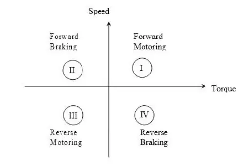
For better understanding of the above notations, let us consider operation of hoist in four quadrants as shown in the figure. Direction of motor and load torques and direction of speed are marked by arrows.
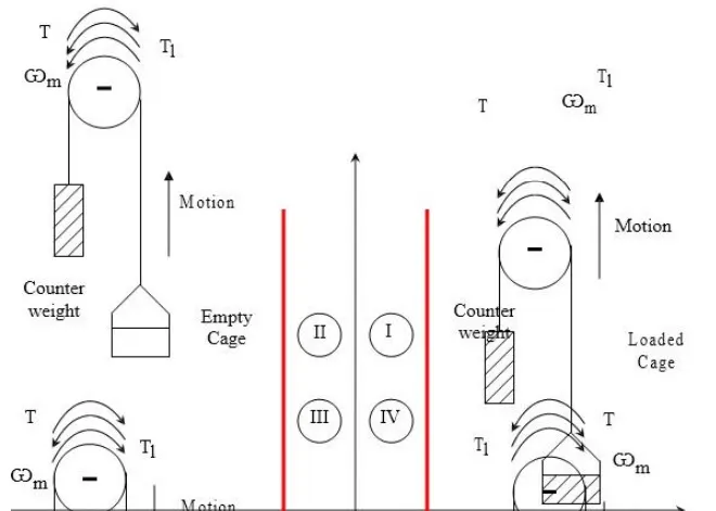
A hoist consists of a rope wound on a drum coupled to the motor shaft one end of the rope is tied to a cage which is used to transport man or material from one level to another level . Other end of the rope has a counter weight. Weight of the counter weight is chosen to be higher than the weight of empty cage but lower than of a fully loaded cage.
Forward direction of motor speed will be one which gives upward motion of the cage. Load torque line in quadrants I and IV represents speed-torque characteristics of the loaded hoist. This torque is the difference of torques due to loaded hoist and counter weight. The load torque in quadrants II and III is the speed torque characteristics for an empty hoist.
This torque is the difference of torques due to counter weight and the empty hoist. Its sigh is negative because the counter weight is always higher than that of an empty cage. The quadrant I operation of a hoist requires movement of cage upward, which corresponds to the positive motor speed which is in counter clockwise direction here. This motion will be obtained if the motor products positive torque in CCW direction equal to the magnitude of load torque TL1.
Since developed power is positive, this is forward motoring operation. Quadrant IV is obtained when a loaded cage is lowered. Since the weight of the loaded cage is higher than that of the counter weight.It is able to overcome due to gravity itself.
In order to limit the cage within a safe value, motor must produce a positive torque T equal to TL2 in anticlockwise direction. As both power and speed are negative, drive is operating in reverse braking operation. Operation in quadrant II is obtained when an empty cage is moved up. Since a counter weigh is heavier than an empty cage, its able to pull it up.
In order to limit the speed within a safe value, motor must produce a braking torque equal to TL2 in clockwise direction. Since speed is positive and developed power is negative, it’s forward braking operation.
Operation in quadrant III is obtained when an empty cage is lowered. Since an empty cage has a lesser weight than a counter weight, the motor should produce a torque in CW direction. Since speed is negative and developed power is positive, this is reverse motoring operation. During transient condition, electrical motor can be assumed to be in electrical equilibrium implying that steady state speed torque curves are also applicable to the transient state operation.
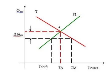
Now, consider the steady state equilibrium point A shown in figure below
Now consider equilibrium point B which is obtained when the same motor drives another load as shown in the figure.
A decrease in speed causes the load torque to become greater than the motor torque, electric drive decelerates and operating point moves away from point B.
Similarly when working at point B and increase in speed will make motor torque greater than the load torque, which will move the operating point away from point B.
In the regenerative braking operation, the motor operates as generator, while it is still connected to the supply. Here, the motor speed is greater than the synchronous speed.
Mechanical energy is converted into electrical energy, part of which is returned to the supply and rest of the energy is last as heat in the winding and bearings of electrical machines pass smoothly from motoring region to generating region, when over driven by the load.
An example of regenerative braking is shown in the figure below. Here an electric motor is driving a trolley bus in the uphill and downhill direction. The gravity force can be resolved into two components in the uphill direction.
One is perpendicular to the load surface (F) and another one is parallel to the road surface Fl. The parallel force pulls the motor towards bottom of the hill.
If we neglect the rotational losses, the motor must produce force Fm opposite to Fl to move the bus in the uphill direction.
Here the motor is still in the same direction on both sides of the hill. This is known as regenerative braking. The energy is exchange under regenerative braking operation is power flows from mechanical load to source.
This operation is indicated as shown in the figure below in the first quadrant.
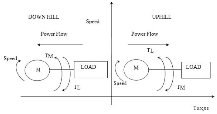
Here the power flow is from the motor to load.
Now we consider that the same bus is traveling in down hill, the gravitational force doesn’t change its direction but the load torque pushes the motor towards the bottom of the hill. The motor produces a torque in the reverse direction because the direction of the motor torque is always opposite to the direction of the load torque.
Here the motor is still in the same direction on both sides of the hill. This is known as regenerative braking. The energy is exchange under regenerative braking operation is power flows from mechanical load to source. Hence, the load is driving the machine and the machine is generating electric power that is returned to the supply.
Regenerative braking of Induction motor:
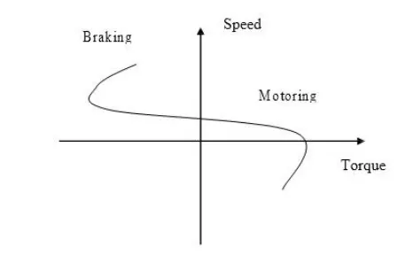
An induction motor is subjected to regenerative braking, if the motor rotates in the same direction as that of the stator magnetic field, but with a speed greater than the synchronous speed. Such a state occurs during any one of the following process.
ü Downward motion of a loaded hoisting mechanism
ü During flux weakening mode of operation of IM.
Under regenerative braking mode, the machine acts as an induction generator. The induction generator generates electric power and this power is fed back to the supply. This machine takes only the reactive power for excitation.
The speed torque characteristic of the motor for regenerative braking is shown in the figure.
Regenerative Braking for DC motor:
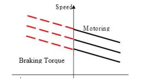
In regenerative braking of dc motor, generated energy is supplied to the source. For this the following condition is to be satisfied.
E > V and Ia should be negative
Modes of Operation:
An electrical drive operates in three modes
ü Steady state
ü Acceleration including Starting
ü Deceleration including Stopping
We know that
T=T1 +J d/dt (ωm)
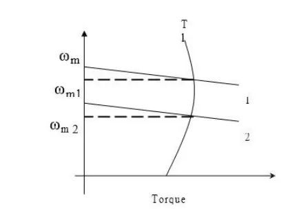
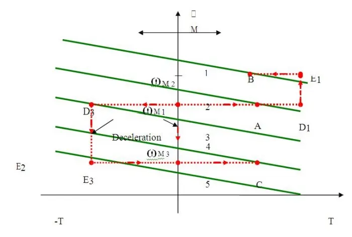
According to the above expression the steady state operation takes place when motor torque equals the load torque. The steady state operation for a given speed is realized by adjustment of steady state motor speed torque curve such that the motor and load torques are equal at this speed. Change in speed is achieved by varying the steady state motor speed torque curve so that motor torque equals the load torque at the new desired speed. In the figure shown below when the motor parameters are adjusted to provide speed torque curve 1, drive runs at the desired speedωm 1 .
Speed is changed to ωm 2 when the motor parameters are adjusted to provide speed torque curve
- When load torque opposes motion, the motor works as a motor operating in quadrant I or III depending on the direction of rotation. When the load is active it can reverse its sign and act to assist the motion. Steady state operation for such a case can be obtained by adding a mechanical brake which will produce a torque in a direction to oppose the motion. The steady state operation is obtained at a speed for which braking torque equal the load torque. Drive operates in quadrant II or IV depending upon the rotation.
Acceleration and Deceleration modes are transient modes. Drive operates in acceleration mode whenever an increase in its speed is required. For this motor speed torque curve must be changed so that motor torque exceeds the load torque. Time taken for a given change in speed depends on inertia of motor load system and the amount by which motor torque exceeds the load torque.
Increase in motor torque is accompanied by an increase in motor current. Care must be taken to restrict the motor current with in a value which is safe for both motor and power modulator. In applications involving acceleration periods of long duration, current must not be allowed to exceed the rated value. When acceleration periods are of short duration a current higher than the rated value is allowed during acceleration.
In closed loop drives requiring fast response, motor current may be intentionally forced to the maximum value in order to achieve high acceleration. Figure shown below shows the transition from operating point A at speed.
Point B at a higher speedωm 2, when the motor torque is held constant during acceleration. The path consists of AD1E1B. In the figure below, 1 to 5 are motor speed torque curves. Starting is a special case of acceleration where a speed change from 0 to a desired speed takes place. All points mentioned in relation to acceleration are applicable to starting.
The maximum current allowed should not only be safe for motor and power modulator but drop in source voltage caused due to it should also be in acceptable limits. In some applications the motor should accelerate smoothly, without any jerk. This is achieved when the starting torque can be increased step lessly from its zero value. Such a start is known as soft start.
3. Explain in a brief about operation of BLDC motor
ANSWER:
Brushless DC electric motors also known as electronically commutated motors (ECMs, EC motors).
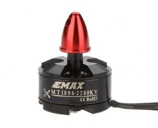
Primary efficiency is a most importent feature for BLDC motors. Because the rotor is the sole bearer of the magnets and it doesn't require any power. i.e. no connections, no commutator and no brushes. In place of these, the motor employs control circuitry. To detect where the rotor is at certain times, BLDC motors employ along with controllers, rotary encoders or a Hall sensor.
Construction of Brushless DC motor
In this motor, the permanent magnets attach to the rotor. The current-carrying conductors or armature windings are located on the stator. They use electrical commutation to convert electrical energy into mechanical energy.
The main design difference between a brushed and brushless motors is the replacement of mechanical commutator with an electric switch circuit. A BLDC Motor is a type of synchronous motor in the sense that the magnetic field generated by the stator and the rotor revolve at the same frequency.
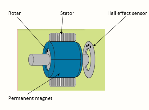
Brushless motor does not have any current carrying commutators. The field inside a brushless motor is switched through an amplifier which is triggered by the commutating device like an optical encoder.
The layout of a DC brushless motor can vary depending on whether it is in “Out runner” style or “Inrunner” style.
-
Outrunner – The field magnet is a drum rotor which rotates around the stator. This style is preferred for applications that require high torque and where high rpm isn’t a requirement.
-
In runner – The stator is a fixed drum in which the field magnet rotates. This motor is known for producing less torque than the out runner style, but is capable of spinning at very high rpm.
Working Principle of Brushless DC motor
BLDC motor works on the principle similar to that of a Brushed DC motor. The Lorentz force law which states that whenever a current carrying conductor placed in a magnetic field it experiences a force. As a consequence of reaction force, the magnet will experience an equal and opposite force. In the BLDC motor, the current carrying conductor is stationary and the permanent magnet is moving.
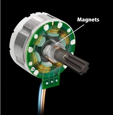
When the stator coils get a supply from source, it becomes electromagnet and starts producing the uniform field in the air gap. Though the source of supply is DC, switching makes to generate an AC voltage waveform with trapezoidal shape. Due to the force of interaction between electromagnet stator and permanent magnet rotor, the rotor continues to rotate.
With the switching of windings as High and Low signals, corresponding winding energized as North and South poles. The permanent magnet rotor with North and South poles align with stator poles which causes the motor to rotate.
BLDC motor works on the principle similar to that of a conventional DC motor, i.e., the Lorentz force law which states that whenever a current carrying conductor placed in a magnetic field it experiences a force. As a consequence of reaction force, the magnet will experience an equal and opposite force. In case BLDC motor, the current carrying conductor is stationary while the permanent magnet moves.
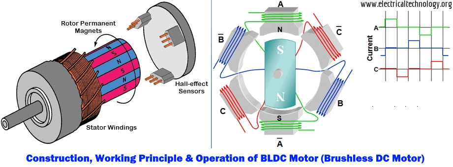
When the stator coils are electrically switched by a supply source, it becomes electromagnet and starts producing the uniform field in the air gap. Though the source of supply is DC, switching makes to generate an AC voltage waveform with trapezoidal shape. Due to the force of interaction between electromagnet stator and permanent magnet rotor, the rotor continues to rotate.
Consider the figure below in which motor stator is excited based on different switching states. With the switching of windings as High and Low signals, corresponding winding energized as North and South poles. The permanent magnet rotor with North and South poles align with stator poles causing motor to rotate.
Observe that motor produces torque because of the development of attraction forces (when North-South or South-North alignment) and repulsion forces (when North-North or South-South alignment). By this way motor moves in a clockwise direction.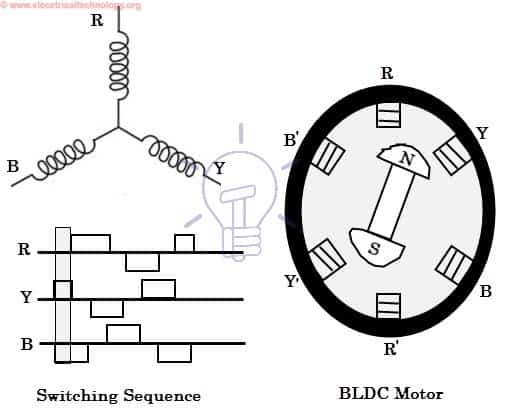
Here, one might get a question that how we know which stator coil should be energized and when to do. This is because; the motor continuous rotation depends on the switching sequence around the coils. As discussed above that Hall sensors give shaft position feedback to the electronic controller unit.
Based on this signal from sensor, the controller decides particular coils to energize. Hall-effect sensors generate Low and High level signals whenever rotor poles pass near to it. These signals determine the position of the shaft.
- You may also read: Terms and Definitions related to Motor Control and Protection
Brushless DC Motor Drive
As described above that the electronic controller circuit energizes appropriate motor winding by turning transistor or other solid state switches to rotate the motor continuously. The figure below shows the simple BLDC motor drive circuit which consists of MOSFET bridge (also called as inverter bridge), electronic controller, hall effect sensor and BLDC motor.
Here, Hall-effect sensors are used for position and speed feedback. The electronic controller can be a microcontroller unit or microprocessor or DSP processor or FPGA unit or any other controller. This controller receives these signals, processes them and sends the control signals to the MOSFET driver circuit.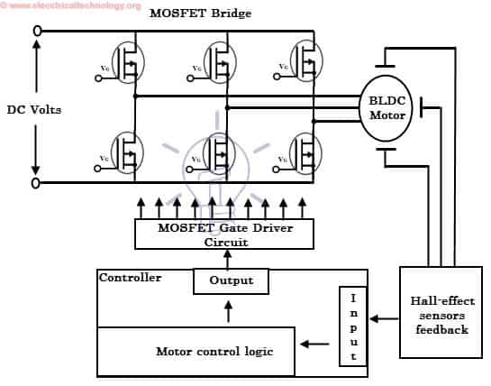
In addition to the switching for a rated speed of the motor, additional electronic circuitry changes the motor speed based on required application. These speed control units are generally implemented with PID controllers to have precise control. It is also possible to produce four-quadrant operation from the motor whilst maintaining good efficiency throughout the speed variations using modern drives.