Week-7 Challenge: DC Motor Control
OBJECTIVES:
1. A. Explain a MATLAB demo model named ‘Speed control of a DC motor using BJT H-bridge’.
B. Comment on the armature current shoot-up from the scope results.
C. Refer to the help section of ‘The Four-Quadrant Chopper DC Drive (DC7) block’. Compare it with the H-bridge model.
2. Develop a 2-quadrant chopper using simulink & explain the working of the same with the relevant results. (Refer to article - Multiquadrant operation of motor )
3. Explain in a brief about operation of BLDC motor.
1. A. Explain a MATLAB demo model named ‘Speed control of a DC motor using BJT H-bridge’.
B. Comment on the armature current shoot-up from the scope results.
C. Refer to the help section of ‘The Four-Quadrant Chopper DC Drive (DC7) block’. Compare it with the H-bridge model.
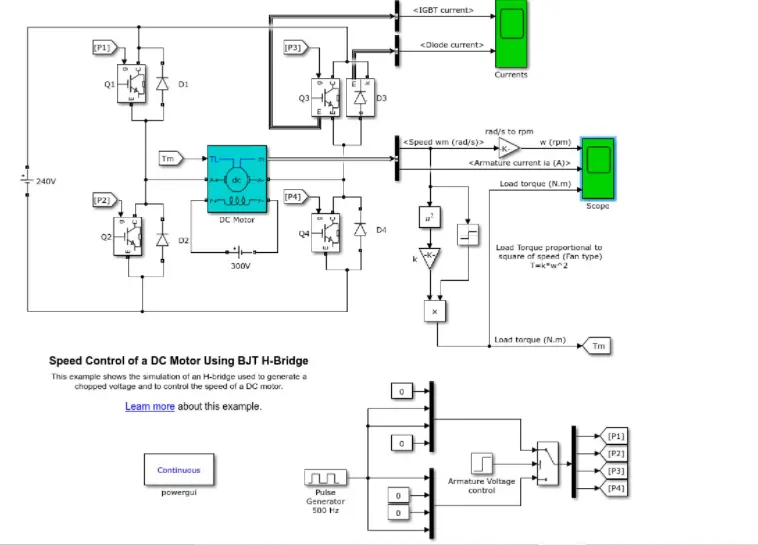
The Bipolar Junction Transistor when used for power switching applications,operates as an IGBT.when it is conducting a forward voltage Vf is developed between collector and emitter.therefore ,the IGBT block can be used to model the BJT Device.
The IGBT block does not simulate the gate current controlling the BJT or IGBT.
the dc motor uses the present model (5HP 24V 1750 RPM).IT SIMULATES a fan type load the armature mean voltage can be varied from 0 to 240 when the duty cycle is varied from 0 to 100%
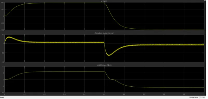
when the simulation is run the motor starts in the positive direction with a duty cycle ratio 75% at t=0.5 sec the armature voltage is suddenly reversed and the motor runs in the negative direction.
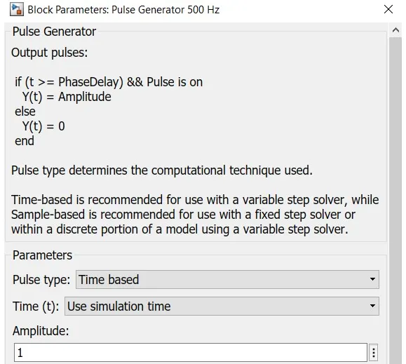
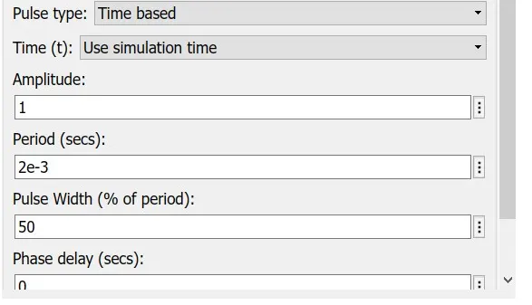
MODIFICATION:
the duty cycle ratio is changed to 50% which is given by the pulse generator block
The result obtained by this modification is as Follows:
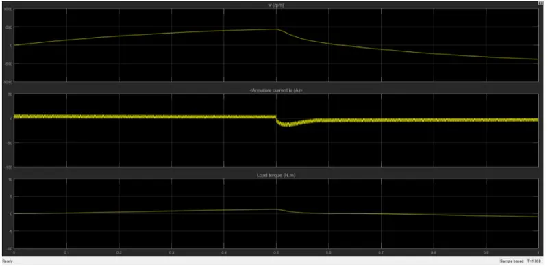
as we can see from the above result graph the armature current rise is little.
LETS REDUCE THE PULSE WIDTH EVEN MORE TO 40
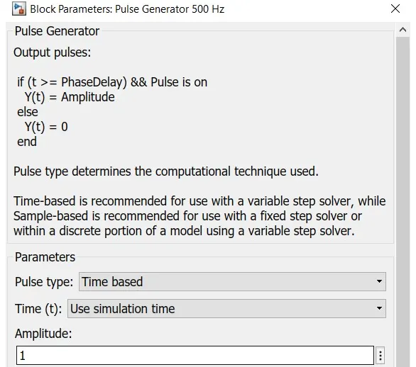
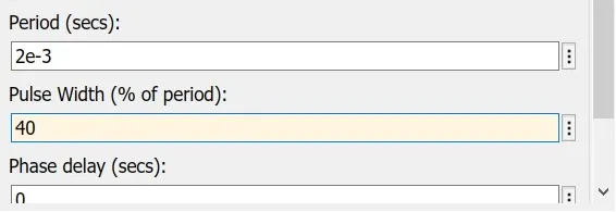
THE RESULT OBTAINED IS:

MANY OF THE RISE OF ARMATURE CURRENT IS REDUCED BY REDUCING THE DUTY CYCLE RATIO
2. Develop a 2-quadrant chopper using simulink & explain the working of the same with the relevant results. (Refer to article - Multiquadrant operation of motor )
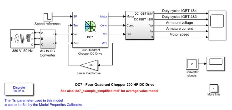
the 200HP DC motor is separately excited with a constant 150V DC field voltage source.the armature voltage is provided by an IGBT converter controlled by two Pl regulators.the converter is fed by a 515v DC bus obtained by rectification of a 380V AC 50Hz voltage source in order to limit the DC bus voltage during dynamic braking mode, a braking the diode rectifier and the DC 7 block
the first regulator is a speed regulator ,followed by a current regulator.the speed regulator outputs the armature current reference used by the armature current controlled in order to obtain the electromagnetic torque needed to reach the desired speed.
the current regulator controls the armature current by computing the appropriate duty ratios of the 5KHz pulses of the four IGBT devices.
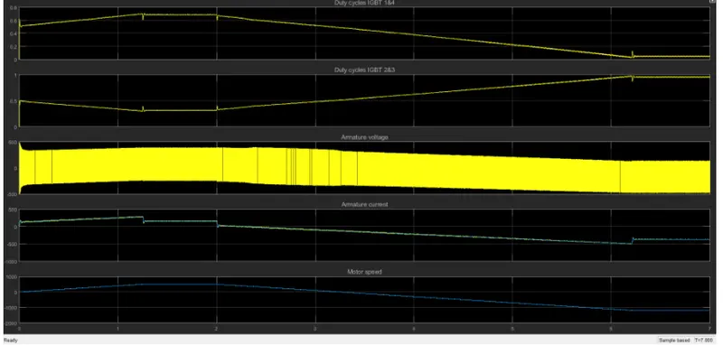
the main disadvantage of this drive ,compared with other DC drives ,is that it can operate in all four quadrants.in addition due to use of high switching frequency DC-DC converters a lower armature current ripple is obtained.
3. Explain in a brief about operation of BLDC motor.
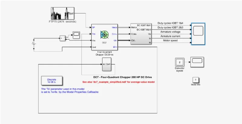
The DC7 Block is modified with addition of blocks to make a suitable EV model
the speed is reference is replaced with drive cycle.
ac source is replaced by the DC voltage source and a current sensor is added in series to measure the flow of current and to view that measure of the current a scope is connected.
the input of the subsystem is the output speed of the dc chooper block,the output of the subsystem block is given to the torque input port of the dc chooper block
THE RESULTANT GRAPHS OBTAINED ARE AS FOLLOWS:
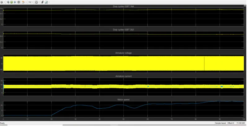
the duty cycles of the IGBT are kept constant through out as 50% for abetter armature current flow.
the armature voltage flow through is smoother and its pulse is around +50 to -50
here we have used FTP75 drivecycle whose first 20 seconds are at rest and the acceleration starts after 20 seconds as we can observe that the motor speed increase and the armature current also rises slightly to meet the demanded acceleration.