Week-7 Challenge: DC Motor Control
To Run and Explain MATLAB demo model named “Speed control of a DC motor using BJT H-bridge”
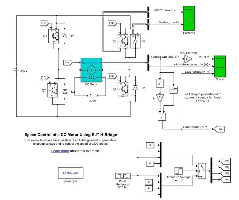
The Bipolar Junction Transistor (BJT) when used for power switching applications operates as an IGBT. When it is conducting (BJT operating in the saturated region), a forward voltage Vf is developed between collector and emitter (in the range of 1 V). Therefore, the IGBT block can be used to model the BJT device.
The IGBT block does not simulate the gate current controlling the BJT or IGBT. The switch is controlled by a Simulink signal (1/0). The DC motor uses the preset model (5 HP 24V 1750 rpm). It simulates a fan type load (where Load torque is proportional to square of speed). The armatures mean voltage can be varied from 0 to 240 V when the duty cycle (specified in the Pulse Generator block) is varied from 0 to 100%.
The H-bridge consists of four BJT/Diode pairs (BJT simulated by IGBT models). Two transistors are switched simultaneously: Q1 and Q4 or Q2 and Q3. When Q1 and Q4 are fired, a positive voltage is applied to the motor and diodes D2-D3 operate as free-wheeling diodes when Q1 and Q4 are switched off. When Q2 and Q3 are fired, a negative voltage is applied to the motor and diodes D1-D4 operate as free-wheeling diodes when Q2 and Q3 are switched off.
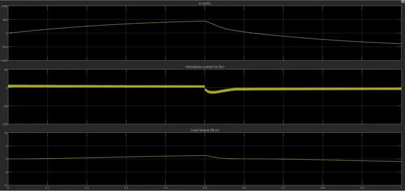
The motor starts in the positive direction with a duty cycle of 75% (mean DC voltage of 180V). At t= 0.5 sec., the armature voltage is suddenly reversed and the motor runs in the negative direction.
'Scope' shows motor speed, armature current and load torque and 'Currents' shows currents flowing in BJT Q3 and diode D3.
SWITCHES:
Q1 and Q2 – Forward Motoring.
Q2 and Q3 – Reverse Motoring.
This formation is called an H-Bridge, An H-bridge is an arrangement of transistor that allows a circuit full control over a standard Electric DC Motor. The DC Motor is connected to battery and the Mechanical Input of DC Motor is initiated as torque.
Torque for Mechanical input of DC motor also switched by Goto and From
The Output of DC motor is connected with “BUS sector” whereas the Speed is plotted in the Scope. A conversion of Speed from rad/sec to rpm is held between the BUS sectors to scope using converter block.
Comment on the armature current shoot-up from the scope results
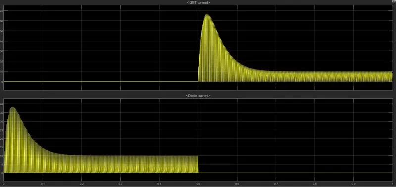
in the Current output the amount of circuit acted is shown as the graphical representation during the period of duty cycle. The scope shows IGBT current and Diode current passed in the Quadrant Q3 and D3 (as initial current is in diode to start the circuit is in D3 diode).
Where Q3 represent as IGBT current and D3 is represented as Diode current in scope.
The Graph shows that when the Switch Q3 is OFF on the Starting Stage of Current flow and Diode current is on that stage. During the 0.5 sec of time D3 switch is ON that are given according to Pulse generator (step time in armature voltage control of 0.5)and after the time period of 0.5 sec D3 switch is OFF and IGBT current is acted after0.5 sec and Q3 switch remains ON.
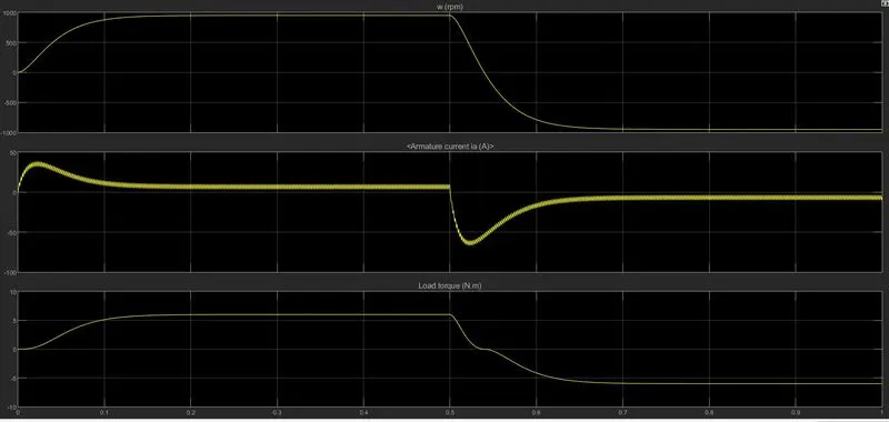
The Speed and Armature current is obtained by the DC Motor and Load Torque is calculated by load torque proportional to square of speed
In Starting point, there is a sudden Shoot-up is acted.
In this Scope shows that speed is increased in certain period of Time and at that time armature current is positive whereas Load Torque also moves forward
Comment on the armature current shoot-up from the scope results
in the Current output the amount of circuit acted is shown as the graphical representation during the period of duty cycle. The scope shows IGBT current and Diode current passed in the Quadrant Q3 and D3 (as initial current is in diode to start the circuit is in D3 diode).
Where Q3 represent as IGBT current and D3 is represented as Diode current in scope.
The Graph shows that when the Switch Q3 is OFF on the Starting Stage of Current flow and Diode current is on that stage. During the 0.5 sec of time D3 switch is ON that are given according to Pulse generator (step time in armature voltage control of 0.5)and after the time period of 0.5 sec D3 switch is OFF and IGBT current is acted after0.5 sec and Q3 switch remains ON.
The Speed and Armature current is obtained by the DC Motor and Load Torque is calculated by load torque proportional to square of speed
In Starting point, there is a sudden Shoot-up is acted.
In this Scope shows that speed is increased in certain period of Time and at that time armature current is positive whereas Load Torque also moves forward
BY CHANGING THE PULSE GENERATOR INPUT VALUE (TO REDUCE THE SHOOT UP OF ARMATURE CURRENT).
One simple and easy way to control the Speed of a Motor is to Regulate the Amount of Voltage across its Terminals and this can be achieved using “Pulse Width Modulation”.
For Experimental Section we will reduce the Pulse width (i.e. refer as DUTY CYCLE) of Pulse generator block as 50% at the same time period.
The Inputs of P1, P2, P3 and P4 are also changed according to the drive cycle. When the Q1 and Q4 switch is ON the Motor is generated as Forward direction that state Q3 switch and Q2 switch is in OFF.
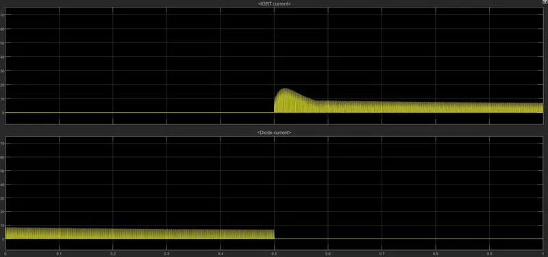
Here we see that the sudden shoot up is not acted by comparing with 75 of pulse width. Same cycle time is followed in this experiment also.
In this observation starting current is generated as Diode current for time period of 0.5 sec , then IGBT current is acted while diode current is being stopped.
This graph shows when the switch Q3 is OFF on the starting stage of current flow and Diode current is ON at that stage.
During the 0.5 sec of time D3 switch is ON that is given according to the Pulse generator and after the time period of 0.5 sec D3 switch is OFF. An IGBT current is acted after0.5sec and Q3 switch remains ON.
There will be little variation as shown in graph at the starting point of current but the complete reduction of Shoot-Up are not held here.
Refer to the help section of ‘The Four-Quadrant Chopper DC Drive (DC7) block’. Compare it with the H-bridge model
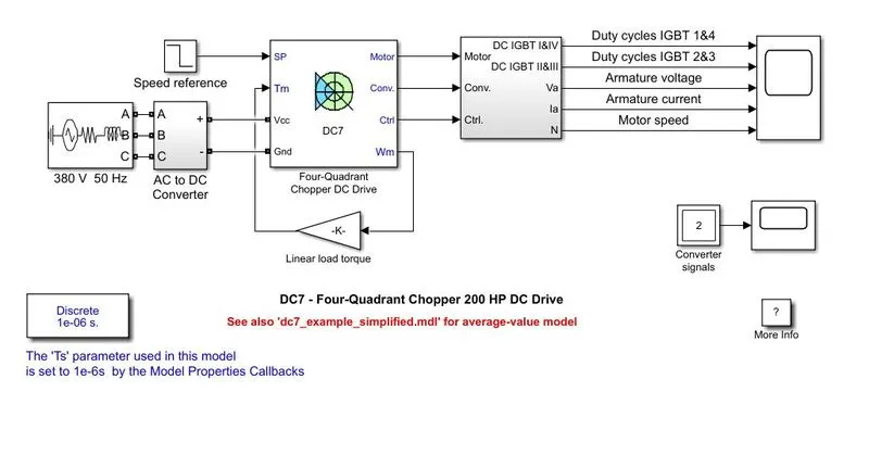
The 200 HP DC motor is separately excited with a constant 150 V DC field voltage source. The armature voltage is provided by an IGBT converter controlled by two PI regulators. The converter is fed by a 515 V DC bus obtained by rectification of a 380 V AC 50 Hz voltage source. In order to limit the DC bus voltage during dynamic braking mode, a braking chopper has been added between the diode rectifier and the DC7 block. The first regulator is a speed regulator, followed by a current regulator. The speed regulator outputs the armature current reference (input.) used by the current controller in order to obtain the electromagnetic torque needed to reach the desired speed. The speed reference change rate follows acceleration and deceleration ramps in order to avoid sudden reference changes that could cause armature overcurrent and destabilize the system. The current regulatory controls the armature current by computing the appropriate duty ratios of the 5 kHz pulses of the four IGBT devices (Pulse Width Modulation). For proper system behavior, the instantaneous pulse values of IGBT devices 1 and 4 are opposite to those of IGBT devices 2 and 3. This generates the average armature voltage needed to obtain the desired armature current. In order to limit the amplitude of the current oscillations, a smoothing inductance is placed in series with the armature circuit.
Results
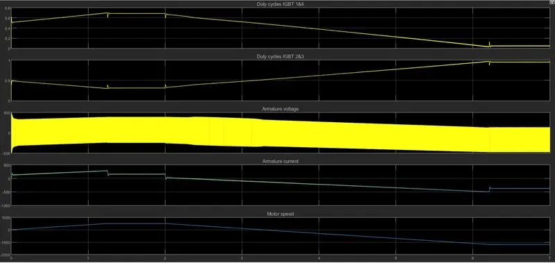
In four Quadrant Chopper DC drive distributes required current supply for each sector and it consist of 4 quadrants like Forward Motoring, Regenerative Braking, Reverse Motoring and Reverse Regenerative Braking. Whereas in H-bridge supplies an irregular current for each sector that causes voltage Fluctuation in armature current; it consist of 2 Operation namely they are Forward Motoring , Reverse Motoring.
In Modern Battery Technology Charger use for EV charging uses H-bridge circuit. Whereas a Four Quadrant Operation is required in Industrial as well as Commercial application.
The efficiency is high in Chopper compare with H-bridge and Maintenance is less than H-bridge.
In Robotic Technology, H-bridge circuit is used; some other application of Four Quadrant Operation is Engine Test Loading Systems.
In H-bridge we need to change Polarity which turns into opposite direction to control the motor whereas in chopper model we need to interrupt one signal under control of another.
COMPARISON OF FOUR-QUADRANT CHOPPER DC DRIVE (DC7) WITH H-BRIDGE:
|
BJT H-Bridge Drive |
FOUR QUADRANT CHOPPER Drive |
|
It’s used for changing the direction of the Motor (forward and reverse). |
Here the Motor can be Operated in 4 different Mode (Forward Motoring and Braking, Reverse Motoring and Braking). |
|
Regenerative Braking cannot be available. |
Regenerative Braking can be Achieved. |
|
The source is of Fixed DC supply. |
The Source is an AC supply which can be rectified to DC varying supply. |
|
The motor speed reference cannot be fed |
The motor speed reference can be fed. |
|
The armature current shoots up during the phase transition. |
The armature current doesn’t shoot up to the value of BJT H-bridge but for low voltage value it’s negligible. |
|
Less control of the Vehicle. |
Better control of the Vehicle. |
|
Signals are continuous. |
Signals are not continuous and they are discrete. |
Develop a 2-quadrant chopper using simulink & explain the working of the same with the relevant results.
Class C Chopper
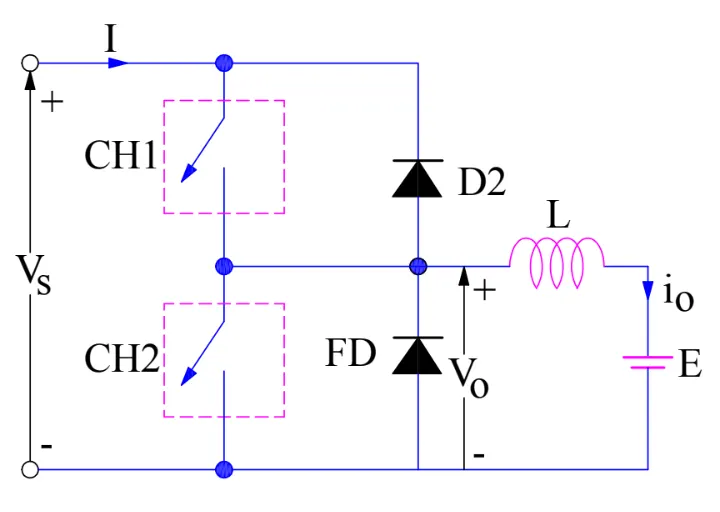
At first we turn on Switch 1 (CH1) the supply current will flow + to – Voltage supply, which will charge the inductor in the circuit with polarity ( + - ), current is positive voltage is positive.
Now as the inductor is getting charged by polarity ( + - ) If now the Switch1 (CH1) is turned OFF, then the inductor is discharge by changing its Polarity ( - + ) and current flow in Loop from inductor to battery to diode (D2)and continues. One can observe is current direction (I0) is as well as voltage is positive. Which are the parameters for 1st quadrant.
Now as if we Press Switch 2 (CH2), EMF of load will charge the Inductor (L), and that current will flow from E to L to CH2 Loop.
An as current is flowing the Loop the Inductor will get charge with polarity ( - + ). During that Time Period Inductor is Storing Energy, current is negative but Output voltage is Positive by the Load EMF.
The above condition are of 2 Quadrant current (-) voltage (+). Now if the switch2 (CH2) is Turned OFF, then the Inductor (L) will release its energy via Diode D1.
Now Inductor will change its polarity from (- +) To (+ - ) and it will release its energy so, Diode 1 will come in Forward bias there by completing the Loop (from inductor to D1 to Vs to E and then again back to E ). Direction of current is in opposite direction of actual positive current of circuit, but Output voltage is Positive
SIMULINK MODEL

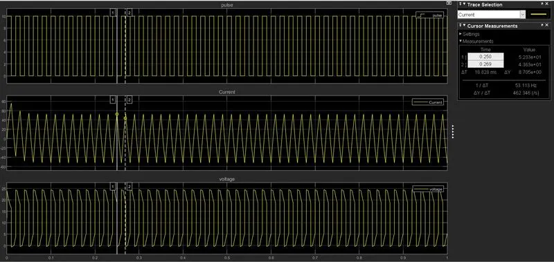
In above model Series RLC band block is used as (L) with default value 1 mill H. Open logical operator and select NOT in Operation options, connects its Input to output of PULSE Generator block. The reason we use NOT gate to ensure both the Switches does not conduct simultaneously if they do so supply will be short-circuited.
We will be giving the tapping for the PULSE gate terminal for 1 switch CH1and from NOT gate we are giving it to other switch CH2. So if CH1 is conducting CH2 will not conduct because we are using the NOT gate.
Once done we will be measuring the voltage by connecting its 1 port at staring of inductor and other to DC2 supply which is connected adjacent.
And output is connect to 1 of the 3 port of scope input, current Measurement port is also connected to 2 port of Scope and 3 port is taken from output of PULSE Generator.
Double click on main DC Voltage supply and set amplitude (V) to 24v and for adjacent DC2 supply set amplitude as 12v.
Open Pulse generator block set amplitude to 10 for better viewing, time period set to 0.02 sec, pulse width is 50 (because we 50 % to be ON and 50% to be OFF) .i.e. NOT gate is ON when 50% OFF
Explain in brief about Operation of Brushless DC Motor (BLDC).
BLDC Motor
Brushless DC Motors or BLDC Motors have become a significant contributor of the modern drive technology. Their rapid gain in popularity has seen an increasing range of applications in the fields of Consumer Appliances, Automotive Industry, Industrial Automation, Chemical and Medical, Aerospace and Instrumentation.
A Brushless DC Motor is similar to a Brushed DC Motor but as the name suggests, a BLDC doesn’t use brushes for commutation but rather they are electronically commutated. In conventional Brushed DC Motors, the brushes are used to transmit the power to the rotor as they turn in a fixed magnetic field.
As mentioned earlier, a BLDC motor used electronic commutation and thus eliminates the mechanically torn brushes.
Construction of BLDC Motor
The main design difference between a brushed and brushless motors is the replacement of mechanical commutator with an electric switch circuit. Keeping that in mind, a BLDC Motor is a type of synchronous motor in the sense that the magnetic field generated by the stator and the rotor revolve at the same frequency. Brushless Motors are available in three configurations: single phase, two phase and three phase. Out of these, the three phase BLDC is the most common one.
The structure of the stator of a BLDC Motor is similar to that of an induction motor. It is made up of stacked steel laminations with axially cut slots for winding. The winding in BLDC are slightly different than that of the traditional induction motor.
Generally, most BLDC motors consist of three stator windings that are connected in star or ‘Y’ fashion (without a neutral point). Additionally, based on the coil interconnections, the stator windings are further divided into Trapezoidal and Sinusoidal Motors.
The rotor part of the BLDC Motor is made up of permanent magnets (usually, rare earth alloy magnets like Neodymium (Nd), Samarium Cobalt (SmCo) and alloy of Neodymium, Ferrite and Boron (NdFeB)).
Based on the application, the number of poles can vary between two and eight with North (N) and South (S) poles placed alternately. The following image shows three different arrangements of the poles. In the first case, the magnets are placed on the outer periphery of the rotor.
Since there are no brushes in a BLDC Motor, the commutation is controlled electronically. In order to rotate the motor, the windings of the stator must be energized in a sequence and the position of the rotor (i.e. the North and South poles of the rotor) must be known to precisely energize a particular set of stator windings.
A Position Sensor, which is usually a Hall Sensor (that works on the principle of Hall Effect), is generally used to detect the position of the rotor and transform it into an electrical signal. Most BLDC Motors use three Hall Sensors that are embedded into the stator to sense the rotor’s position.
The output of the Hall Sensor will be either HIGH or LOW depending on whether the North or South pole of the rotor passes near it. By combining the results from the three sensors, the exact sequence of energizing can be determined.
Working Principle
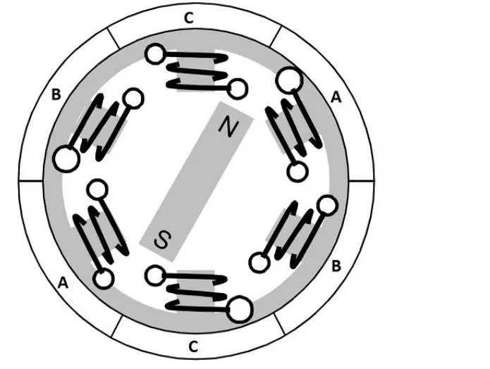
Consider the following setup of three windings in the stator designated A, B and C. For the sake of understanding, let us replace the rotor with a single magnet.
We know that when a current is applied through a coil, a magnetic field is generated and the orientation of the field lines i.e. the poles of the generated magnet will depend on the direction of the current flowing through the coil.
Using this principle, if we supply current to the coil A so that it will generate a magnetic field and attract the rotor magnet. The position of the rotor magnet will shift slightly clockwise and will align with A.
If we now pass current through coils B and C one after the other (in that order), the rotor magnet will rotate in clock wise direction
To increase efficiency, we can wind the opposite coils using a single coil so that we get double attraction. Further increasing the efficiency, we can energize two coils at the same time so that one coil will attract the magnet and the other coil will repel it. During this time, the third will be idle.
For a complete 360 rotation of the rotor magnet, six possible combinations of the coils A, B and C are applicable and are shown in the following timing diagram.
Driving Brushless DC Motors
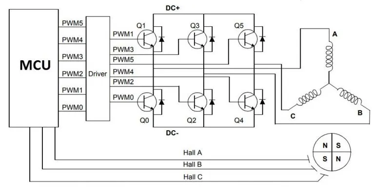
If stator and rotor are essential parts of a BLDC Motor that are integral to it, then the driving electronics are equally essential. Block diagram of a typical Brushless DC Motor control or drive system is shown in the following image.
This drive circuitry is often known as Electronic Speed Controller System or simply an ESC. One common setup is called the Full Bridge Drive Circuit. It consists of an MCU with PWM outputs, six MOSFETS for the three phases of the stator windings, feedback from the Hall sensors and some power supply related components.
Advantages of BLDC Motors
No wear and tear (due to absence of brushes)
High efficiency
Better speed vs torque characteristics
Long life
Less noise or noiseless operation
Significantly higher RPM
Applications of Brushless DC Motors
Some of the areas of applications of BLDC Motors are mentioned below:
Single speed applications
Adjustable speed applications
Position control Low noise applications
High speed applications