Week - 4
Aim: To implement control logic of a 'washing machine' using stateflow.
Conditions:
If power is ON, the system should be activated.
The process should take place when water supply is available or else stop the process with indicating LED.
Soaking time is 200 seconds.
Washing time is 100 seconds. Rinsing time is 20 seconds.
Drying time is for 50 seconds.
After completion of all process finished LED should glow.
Procedure:
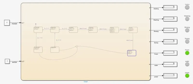
Add chart block with in MATLAB Simulink for the logic that need to be applied for washing machine. Chart block is a state flow logic used in this model. After adding, open it by double clicking on it
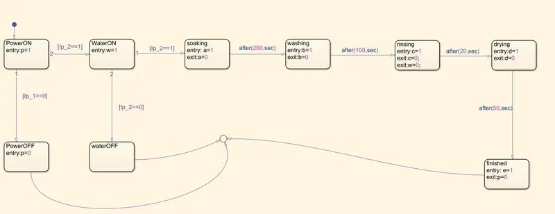
In charts logics are applied by using states and connections. Add states for each and every process, starting with power. Process takes place when power is ON and OFF conditions. If power is ON, the process continues for next step, else terminates the whole logic.
Ip_1, Ip_2 is configure as input port and a, b, c, d, e, p, w is configure as output port.
Ip_1 is used to indicate power input and Ip_2 is used to indicate water input. When power is on the entry state for the power block is P=1 and when power is off the state changes to P=0.
The process also should continue when water supply is available only. To achieve this we apply the joining condition is [Ip_2==1]. For no water we join to another state with condition [Ip_2==0].
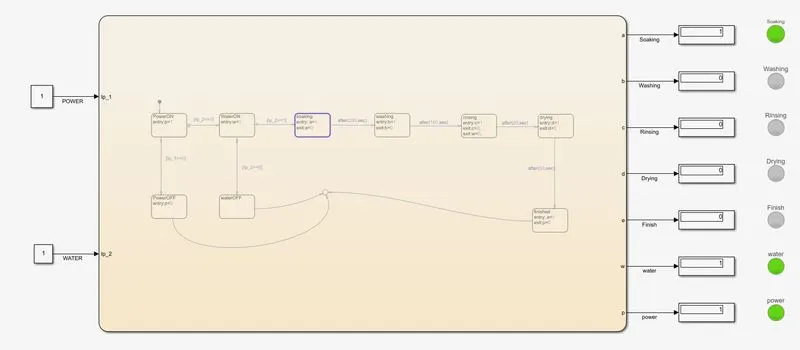
After power and water both are available we go to further state which is soaking with an entry a=1 and after process exit a=0 which is connected to washing by condition after (200, sec) to get 200 seconds delay.
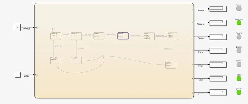
In washing the entry state is b=1 washing start and to exit b=0 which is connected to rinsing by condition after (100, sec) to get 100 seconds delay.
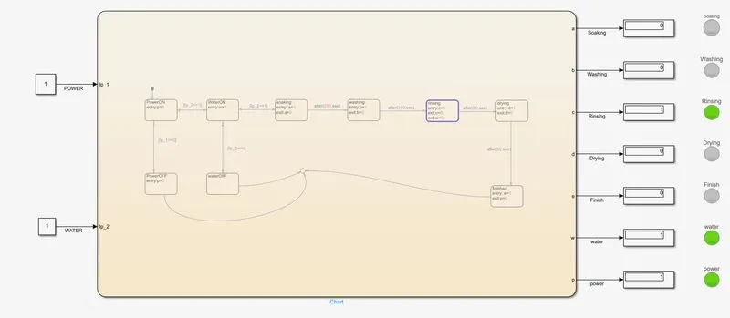
In rinsing we stop the water by giving condition w=0 and entry condition c=1, to exit rinsing we give exit: c=0, which is connected to drying by condition after (20, sec) to get 20 seconds delay.
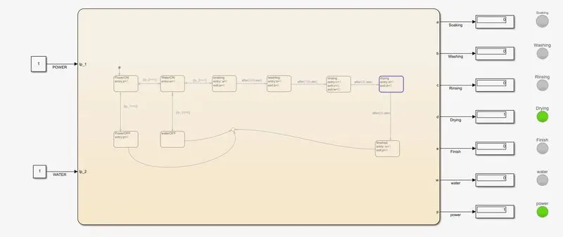
In drying state we give entry: d=1, and to exit drying we exit: d=0, which is connected to finish state by the condition after (50, sec) to get 50 seconds delay.
In finish state we give entry: e=1, to indicate finish process.
State flow chart for Washing Machine
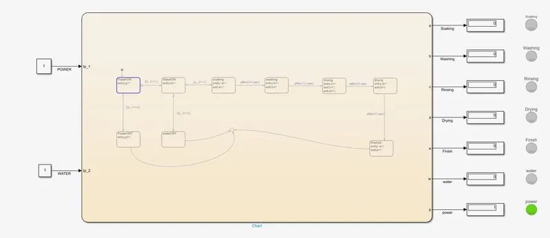
Process
Power ON
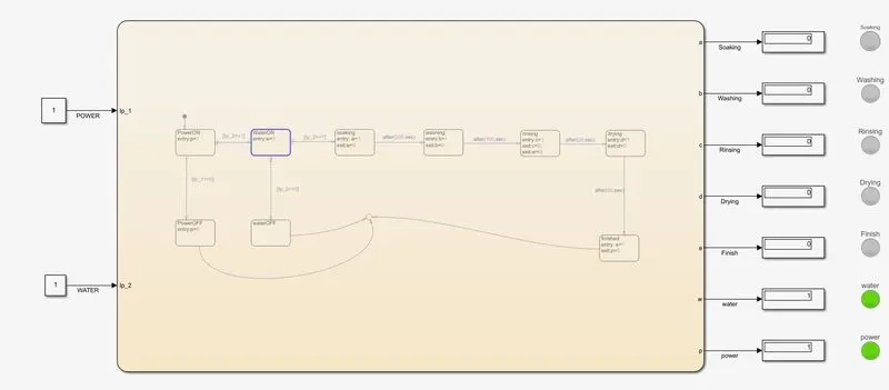
Water ON
In Soaking state
In Washing state
In Rinsing state
In Drying state
Process Finished
2)
Aim: To make a Simulink chart for 'gear shift' logic under certain conditions.
Conditions:
Speed Range(kmph) Gear
0 to 15 1
16 to 25 2
26 to 40 3
41 to 60 4
Above 61 5
Procedure:
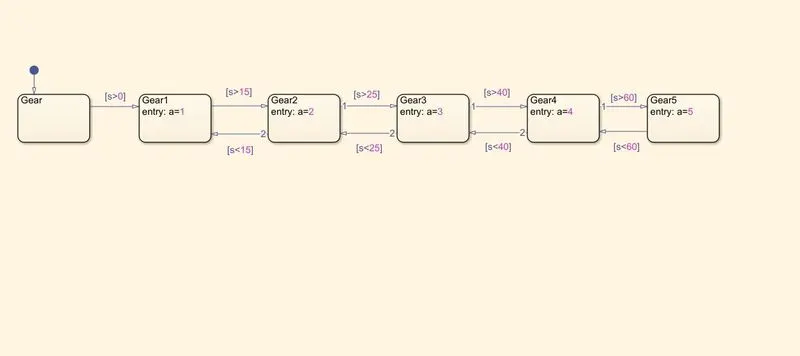
Create states for each and every gear that needed to be changed. First create a state for input taking the values and name it as gear
Create another state with gear1 and entry as a=1. Join with the previous state with a condition [s>0].
Create a new state for second gear as naming it as gear2. Since there is a range of speed for each and every gear, we use joining in both directions.
Gear1 to gear2 is given by [s>15] and in reverse [s<15].
Create a new state for third gear as naming it as gear3. Gear2 to gear3 is given by [s>25] and in reverse [s<25]
Create a new state for fourth gear as naming it as gear4. Gear3 to gear4 is given by [s>40] and in reverse [s<40]. ><40]
Create a new state for fifith gear as naming it as gear5. Gear4 to gear5 is given by [s>60] and in reverse [s<60]
Give parameters for s, a. Give input for 's' and output for 'a'
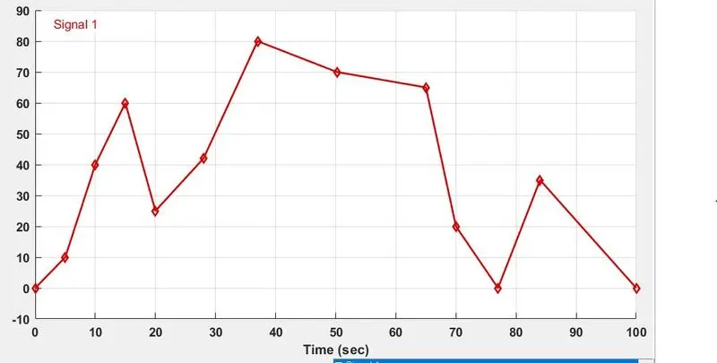
For input speed give random signal with the help of signal builder
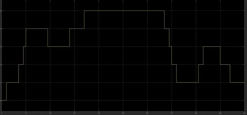
To get output add scope to observe shifting
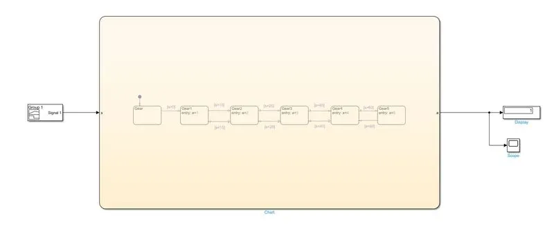
State flow chart for Gear Shift
Speed input of signal builder
Gear shifting graph in scope