Week-7 Challenge: DC Motor Control
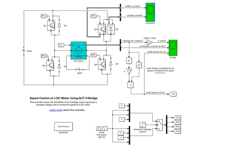 This example shows the simulation of an H-bridge used to generate a chopped voltage and to control the speed of a DC motor.
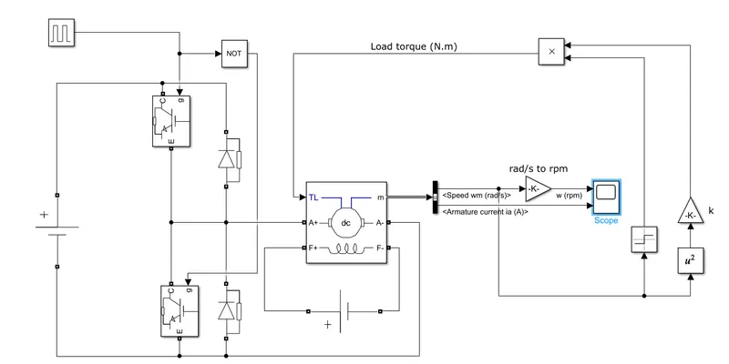
a A DC machine block is used here to represent the DC motor with preset configuration: 5HP 240V 1750RPM Field:300V
b The DC Voltage source block is used to provide field excitation of 300 V and is connected across F+ and F- ports
c To generate the load torque, the speed of the motor is squared and multiplied by a constant value of '6.062e-4' in the gain block.
Load Torque proportional to
square of speed (Fan type)
T=k*w^2
d A step input on the switch block alters the gate pulse input to the IGBTs in the circuit after 0.5s.
e A Pulse generator block is used here with a duty cycle of 0.75 and a frequency of 500 Hz.
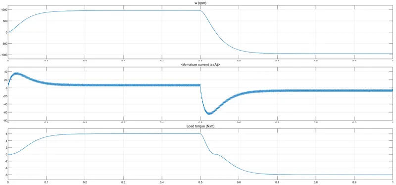
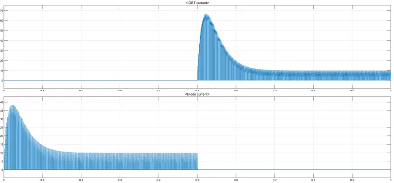
P1 and P4 will conduct upto 0.5s and P3 and P2 will conduct after 0.5 upto stoptime.
2 Armature resistance of a motor is very small,generally less than one ohm,therefore the starting current would be very large.
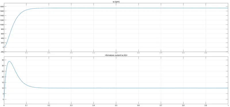
As the motor speed increases, the back emf increses and the difference (V-E) goes on decreasing. This results in the gradual decrease of armature current until the motor attains its stable speed.
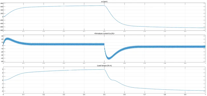
We can change the duty cycle here to change the terminal voltage across the Motor which can limit the starting inrush current.
Output when pulse width= 65 %
C) 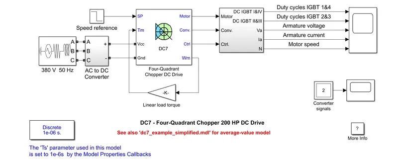
| H-bridge model |
The Four-Quadrant Chopper DC Drive (DC7) block’ |
| switching device is an IGBT/Diode |
switching device is an IGBT/Diode |
| For power_Hbridge we use Fan load, which is proportional to the square of the speed of the motor |
for dc7_example we use linear load, which is directly proportional to the speed of the motor. |
| A DC machine block is used here to represent the DC motor with preset configuration: 5HP 240V 1750RPM Field:300V |
The converter is fed by a 515 V DC bus obtained by rectification of a 380 V AC 50 Hz voltage source. The 200 HP DC motor is separately excited with a constant 150 V DC field voltage source. |
| The operation is open loop. |
This drive features closed-loop speed control with four-quadrant operation. |
2)The model has been attached with the report
Typically, Class C choppers come in two quadrants. It operates in only the first and second quadrants. Voltage output remains positive, while current output can be positive or negative.
Every half cycle of input voltage, one diode and one switch conduct. No two switches are on at the same time, in order to avoid the short circuit.
3)
Brushless DC electric motors also known as electronically commutated motors (ECMs, EC motors).
n the BLDC motor, the current carrying conductor is stationary and the permanent magnet is moving.
When the stator coils get a supply from source, it becomes electromagnet and starts producing the uniform field in the air gap. Though the source of supply is DC, switching makes to generate an AC voltage waveform with trapezoidal shape. Due to the force of interaction between electromagnet stator and permanent magnet rotor, the rotor continues to rotate.
With the switching of windings as High and Low signals, corresponding winding energized as North and South poles. The permanent magnet rotor with North and South poles align with stator poles which causes the motor to rotate.