Week-7 Challenge: DC Motor Control
DC Motor Control
OBJECTIVES :
1. A. Explain a MATLAB demo model named ‘Speed control of a DC motor using BJT H-bridge’.
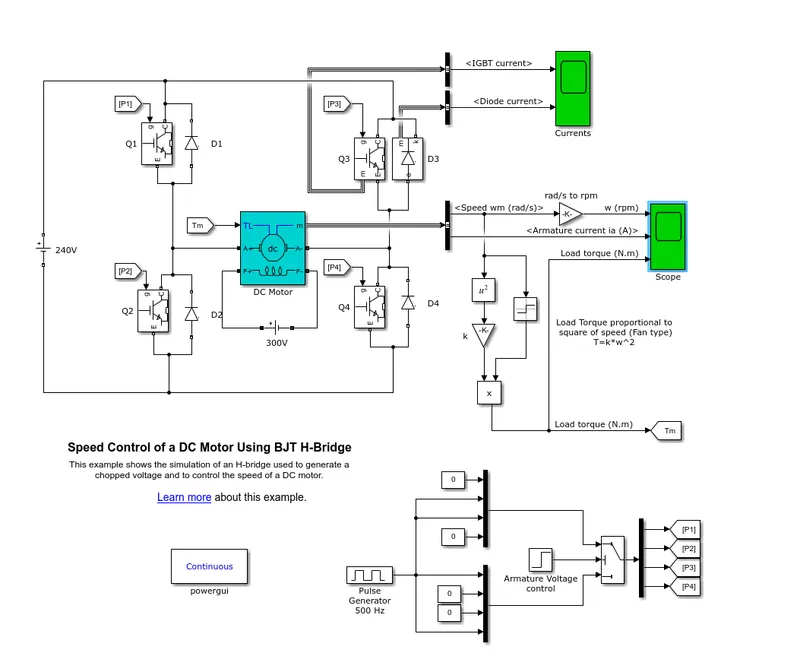
The Bipolar Junction Transistor (BJT) when used for power switching applications, operates as an IGBT. When it is conducting (BJT operating in the saturated region), a forward voltage Vf is developed between collector and emitter (in the range of 1 V). Therefore, the IGBT block can be used to model the BJT device.
The IGBT block does not simulate the gate current controlling the BJT or IGBT. The switch is controlled by a Simulink® signal (1/0). The DC motor uses the preset model (5 HP 24V 1750 rpm). It simulates a fan type load (where Load torque is proportional to square of speed). The armature mean voltage can be varied from 0 to 240 V when the duty cycle (specified in the Pulse Generator block) is varied from 0 to 100%.
The H-bridge consists of four BJT/Diode pairs (BJT simulated by IGBT models). Two transistors are switched simultaneously: Q1 and Q4 or Q2 and Q3. When Q1 and Q4 are fired, a positive voltage is applied to the motor and diodes D2-D3 operate as free-wheeling diodes when Q1 and Q4 are switched off. When Q2 and Q3 are fired, a negative voltage is applied to the motor and diodes D1-D4 operate as free-wheeling diodes when Q2 and Q3 are switched off.
The model below shows the simulation of an H-bridge used to generate a chopped voltage and to control the speed of a DC motor.
Result- When we run the simulation for 1st case with keeping the parameters as default we get the following result in scope.
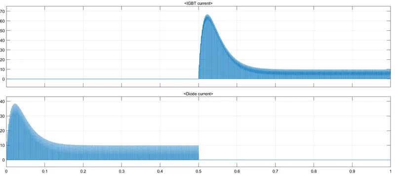
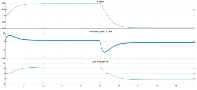
Here in the result above for the plot of current we can observe that at 0.5 sec, the armature voltage is suddenly reversed and the motor runs in the negative direction. So, in the first half cycle, we can see that the motor attains a speed of 1000 RPM and a load torque of 6 Nm. Whereas, for the second half cucle the same values in the negative direction. Here we can see that the armature current of DC motor does not shoot up.
B. Comment on the armature current shoot-up from the scope results.
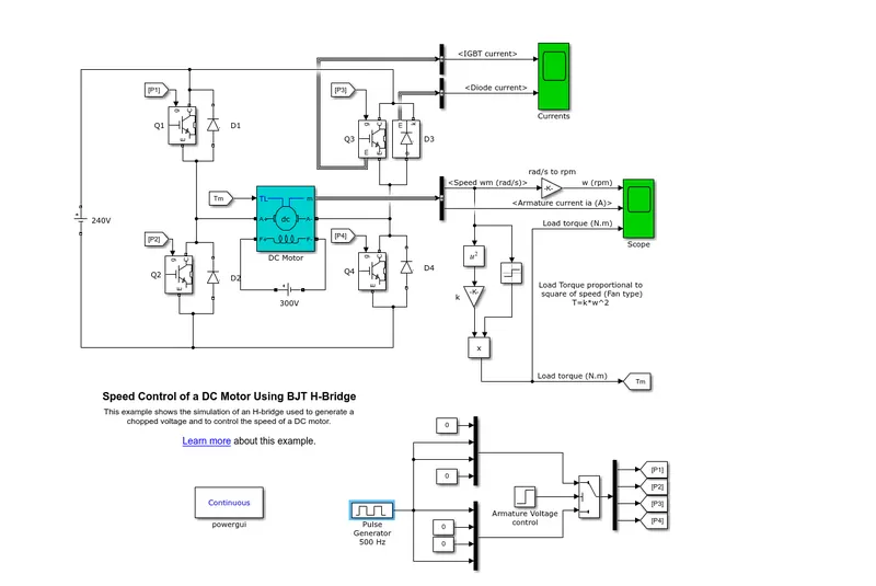
In this case, the simulation is such that the motor starts rotating in positive direction with the duty cycle of 50% with mean voltage of 120V. Scope shows the motor speed, armature current and load torque. The block parameters for pulse generator for this case are as follows

RESULT :
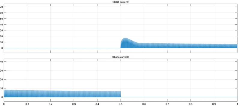
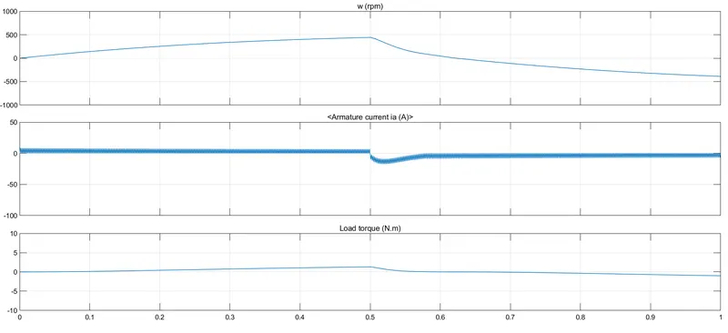
Here in the result above for the plot of current we can observe that at 0.5 sec, the armature voltage is suddenly reversed and the motor runs in the negative direction. So, for 50% duty cycle, in the first half cycle, we can see that motor speed reduced to approx 420 RPM and a load torque of 1.3 Nm respectively. Whereas, for the second half cycle the same values in the negative direction. Here the armature current of DC motor does not shoot up at 50%.
From the above observation we get to know that, as we reduce the pulse width (duty cycle), the motor speed and torque reduces and can attain zero wheras when we increase the value of pulse width gradually the speed of motor and torque also increases gradually to its maximum value.
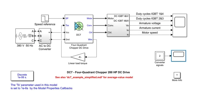
C. Refer to the help section of ‘The Four-Quadrant Chopper DC Drive (DC7) block’. Compare it with the H-bridge model.
RESULT :
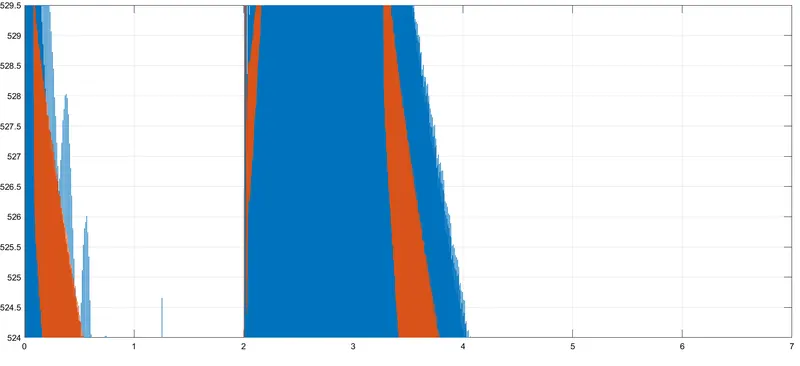
Result
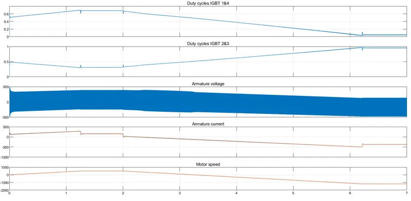
Based on the above simulation performed we get the following result on the scope:
- The plot of duty cycles IGBT 1&4 are exactly opposite to that of duty cycles IGBT 2&3 as the pulse width of IGBT devices 1 and 4 are opposite to those of IGBT devices 2 and 3.
- The desired armature current is obtained from the average armature voltage.
- The armature current follows the current reference very well, with fast response time and small ripples.
- Compare between The Four-Quadrant Chopper DC Drive (DC7) block and the H-bridge model
| Sr. No. | 4 Quadrant Chopper DC7 | H-bridge model (2 Quadrant) |
| 1. | In this cricuit give 4 different outputs. | In this cricuit give 2 different outputs. |
| 2. | More controlling in terms of braking. | Less control (Only forword and reverse) |
| 3. | Cricuit is Separately excited. | Cricuit is Not separately excited. |
| 4. | In this cricuit two PI regulators | In this cricuit no PI regulators used. |
| 5. | Input power supply is AC and use AC to DC Convertor. | Here input power supply is DC. |
| 6. | Use (regenerative)dynamic brake system for produce power. | This system not capable to produce power by using regenerative brake system. |
Objective-2:
Develop a 2-quadrant chopper using simulink & explain the working of the same with the relevant results.
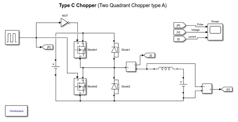
The above model is the model of Type Chopper(Type A Two Quadrant Chopper). In this type of Chopper, the average voltage will be always positive but the average load current might be positive or negative. The two Switches CH1 and CH2 should not be turned on simultaneously as the combined action may cause a short circuit in supply lines. For regenerative braking and motoring these type of chopper configuration is used.
We will always get a positive output voltage V0 as the freewheeling diode FD is present across the load. When the chopper CH1 is on the current flows from source to load. The inductor stores energy. When Ch1 turn OFF the freewheeling diode starts conducting and the output voltage v0 will be equal to Vs. The direction of the load current i0 will be reversed. The current i0 will be flowing towards the source. The load current will be negative when the CH2 is on. The current completes its path through diode D2.
Objective-3:
Explain in a brief about operation of the BLDC motor
Introduction of BLDC:
A brushless DC motor (known as BLDC) is a permanent magnet synchronous electric motor which is driven by direct current (DC) electricity and it accomplishes an electronically controlled commutation system (commutation is the process of producing rotational torque in the motor by changing phase currents through it at appropriate times) instead of a mechanical commutation system. BLDC motors are also referred to as trapezoidal permanent magnet motors. The efficiency of BLDC motors is typically 85 to 90 per cent, whereas brushed type DC motors are 75 to 80 per cent efficient. There are wide varieties of BLDC motors available ranging from small power range to fractional horsepower, integral horsepower and large power ranges.
Diagram:
Construction:
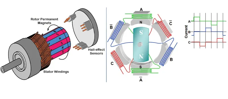
BLDC motors can be constructed in different physical configurations. Depending on the stator windings, these can be configured as single-phase, two-phase, or three-phase motors. However, three-phase BLDC motors with permanent magnet rotor are most commonly used.
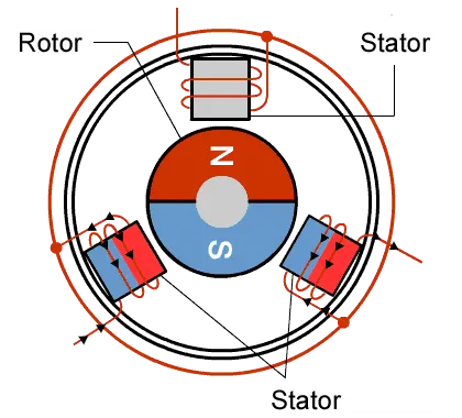
Stator: The stator of a BLDC motor made up of stacked steel laminations to carry the windings. These windings are placed in slots that are axially cut along the inner periphery of the stator. These windings can be arranged in either star or delta. However, most BLDC motors have three-phase star connected stator.
Rotor: BLDC motor incorporates a permanent magnet in the rotor. The number of poles in the rotor can vary from 2 to 8 pole pairs with alternate south and north poles depending on the application requirement. In order to achieve maximum torque in the motor, the flux density of the material should be high.
Hall sensor: Hall sensor provides the information to synchronize stator armature excitation with rotor position. Since the commutation of the BLDC motor is controlled electronically, the stator windings should be energized in sequence in order to rotate the motor. Before energizing a particular stator winding, acknowledgement of rotor position is necessary. So the Hall Effect sensor embedded in the stator senses the rotor position.
Working principle:
BLDC motor works on a principle similar to that of a conventional DC motor, i.e., the Lorentz force law which states that whenever a current-carrying conductor placed in a magnetic field it experiences a force. As a consequence of reaction force, the magnet will experience an equal and opposite force.
Working:
In the case of, BLDC motor, the current-carrying conductor is stationary while the permanent magnet moves. When the stator coils are electrically switched by a supply source, it becomes an electromagnet and starts producing the uniform field in the air gap. Though the source of supply is DC, switching makes to generate an AC voltage waveform with a trapezoidal shape. Due to the force of interaction between the electromagnet stator and permanent magnet rotor, the rotor continues to rotate.
Advantages:
- It has no mechanical commutator and associated problems
- High efficiency due to the use of permanent magnet rotor
- High speed of operation even in loaded and unloaded conditions due to the absence of brushes that limits the speed
- Smaller motor geometry and lighter in weight than both brushed type DC and induction AC motors
- Long-life as no maintenance is required for commutator system
Disadvantages:
- These motors are costly
- The electronic controller required to control this motor is expensive
- Not much availability of many integrated electronic control solutions, especially for tiny BLDC motors
- Requires complex drive circuitry
- Need of additional sensors
Applications:
- Computer hard drives and DVD/CD players
- Electric vehicles, hybrid vehicles, and electric bicycles
- Industrial robots, CNC machine tools, and simple belt-driven systems
- Washing machines, compressors and dryers
- Fans, pumps and blowers