Radar Mast & Final Assembly of Yacht
MODELLING OF SUNSEEKER PREDATOR YACHT
Objective
The objective off this project is solely aimed at applying all surface modelling tools in designing a part(s) and then use the surface as reference to assemble the parts of the Sunseeker Predator Yacht in SolidWorks.
Introduction
In this project, we will design individual parts of the Sunseeker Predator Yacht in SolidWorks by making use of various modelling tools combined with solid modelling features, projected curves and reference geometries to eventually mate all parts using a reference surface to achieve the fully assembled yacht. All the sketches used to design the sunseeker predator yacht will be constrained with proper dimensional and geometrical constraints enabling us to make any variations during the design process. This technique/ approach that we are going to use in this project is called feature parametric modelling.
Design Approach: The parametric feature-based Bottom-Up approach has been followed in the modelling of this sunseeker predator yacht.
Yacht
Yacht is a sail or power vessel used for pleasure, cruising, or racing. There is no standard definition, so the term applies to such vessels that have a cabin with amenities that accommodate overnight use. To be termed a yacht, as opposed to a boat, such a pleasure vessel is likely to be at least 33 feet (10 m) in length and may have been judged to have good aesthetic qualities.
The Commercial Yacht Code classifies yachts 79 ft (24 m) and over as large. Such yachts typically require a hired crew and have higher construction standards. Further classifications for large yachts are: commercial—carrying no more than 12 passengers, private—solely for the pleasure of the owner and guests, or by flag, the country under which it is registered.
Racing yachts are designed to emphasize performance over comfort. Charter yachts are run as a business for profit. As of 2020 there were more than 15,000 yachts of sufficient size to require a professional crew.
DESIGN METHODOLOGY/APPROACH :
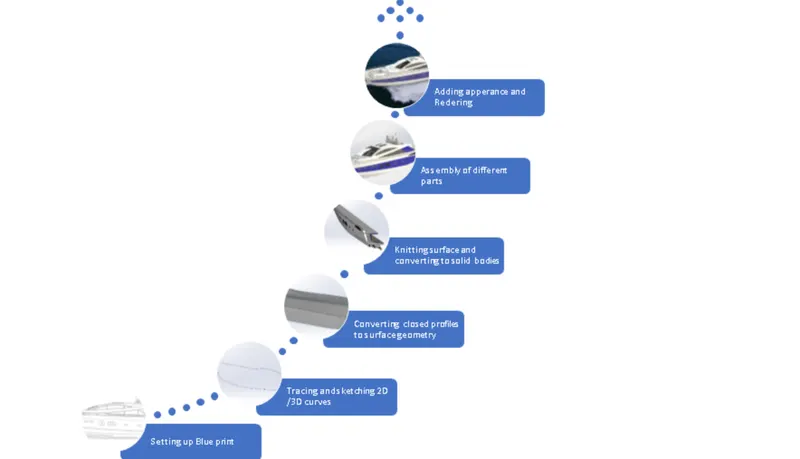
Flow chart :
Name Of Part Modeling :
- Propeller
- Radar
- Hull
- Garage door
- Front seat
- Middle seat
- Rear seat
- Super structure
- Radar mast
Features Specification :
- Sketch
Sketch is a two dimensional representation for converting 2D sketch to 3D modelling. In solidworks , there are different sketch options to create a sketch and these are known as sketch entities – lines, circle, arc , rectangle etc
- Extrude boss
This feature is to convert 2D into solid modeling only when the 2D into a solid modeling only when 2D sketch is completely closed. It also allows to extrude the surface in both directions and also offset is to require distance.
- Fillets
This is to create a curve surface on the profile edges on solid model by selecting the required lines or the faces the fillet also has a feature to select multiple lines which reduce time consumption.
- Extrude cut
It is used to remove materials from a solid model in desired patterns and also it can be extruded with both directions.
- Split tool
This tool is very handy ,when two or more solid body intersect in between or intersect each other then split tool allows to delect unwanted solid body formation gives a clean look.
- Trim entities
There are two types of entities:
- Extend entities- which allows the broken lines to intersect each other and this can be done only in 2D sketch.
- Trim entities- this helps to remove unwanted lines which are intersecting.
- Swept surface
surface generated from section curve positioned along the path.
- Chamfer
It is similar to the fillet feature but in chamfer ,it cuts the solid model intersection area into recurred length and angle.
- Appearance
This adds visual properties to model which give them a materialistic look. There is no effect over physical properties by defining appearance.
- Surface Loft
It create lofted surface between two closed profile in different plane.
- Surface Trim
It trims the surface which is required only when there is a intersection surface, sketch or plane.
- Surface Knit
It create or combine two adjacent non intersecting surface together.
- Delete Face
It completely delete or remove face as required.
- Convert entities
It convert selected sketch entities, edge to sketch segment. This help to save time by eliminating process of re-sketching.
- Reference geometry
This help to create new reference plane, axis, coordinate system and point as required.
- Revolve
This feature helps to revolve 2D geometry or sketch about selected axis, plane, edge and convert it to solid feature.
- Mate Feature
This feature creates a geometric relationship between two parts. To define it with refernce to part we add relation like linear, parallel, concentric, rotational which fix the part in proper way and according requirements.
Following Parts are modelled and assembly :-
Propeller:
As the name suggests, propeller is a device which propels (drive or push forward) an object that transforms rotational power into linear thrust by acting upon a working fluid, such as wate, as we are creating a propeller for our yacht.
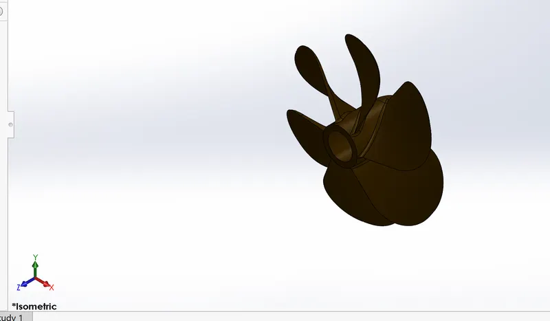
Following commands are used to complete this part :
- Sketch
- Line
- Circle
- Loft
- Rectangle
- Revolve
- Circular pattern
- Extrude cut
Radar:
The term radar was coined as an acronym for ‘Radio Detection and Ranging’. Here we are referring to Marine Radars which are used to detect what objects/ obstacles are around, seeing through darkness, precipitation and poor visibility to safely navigate a ship/boat by avoiding collision. The radar scanner keeps rotating at 360 degree about its vertical axis and is located at the top of the ship/boat. For our radar we will also create and add a text on its surface.
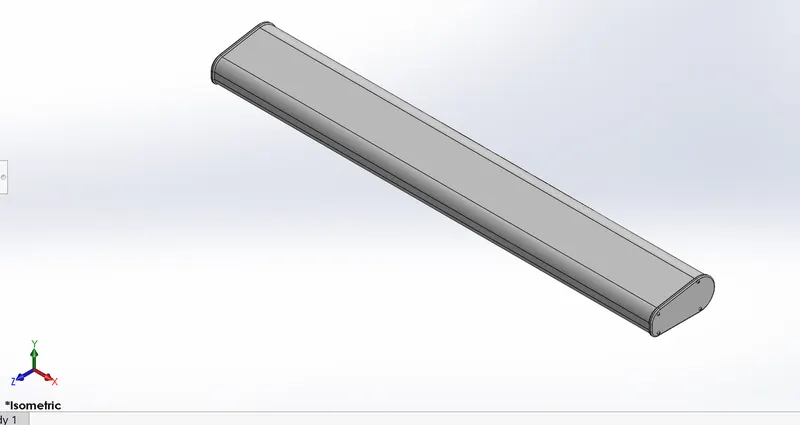
Following commands are used to complete this part :
- Sketch
- Extrude
- Fillet
- Line
- Polygon
- Circle
- Text
- Mirror
Hull:
Hull is the watertight enclosure of the watercraft, which protects the cargo. The hull of a ship directly interacts with water and therefore is the most crucial consideration providing hydrodynamic point of view for designing.
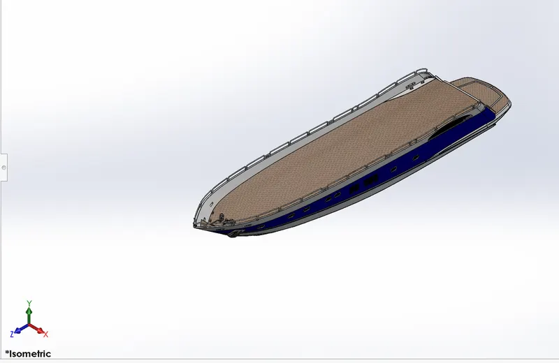
Following commands are used to complete this part :
- Sketch
- Offset
- Entities
- Project curves
- Lofted surface
- Trim surfaces
- Exteuded surfaces
- Knit surface
- Filled surface
- Shell
- Extruded boss
- Fillet
- Chamfer
- Swept boss
- Revolved boss
- Dome
- Helix
- Linear pattern
- 3d sketch
- Mirror
- Split body
- Offset surface
Garage Door
Garage is used to store any essential commodities, vehicles and tools.
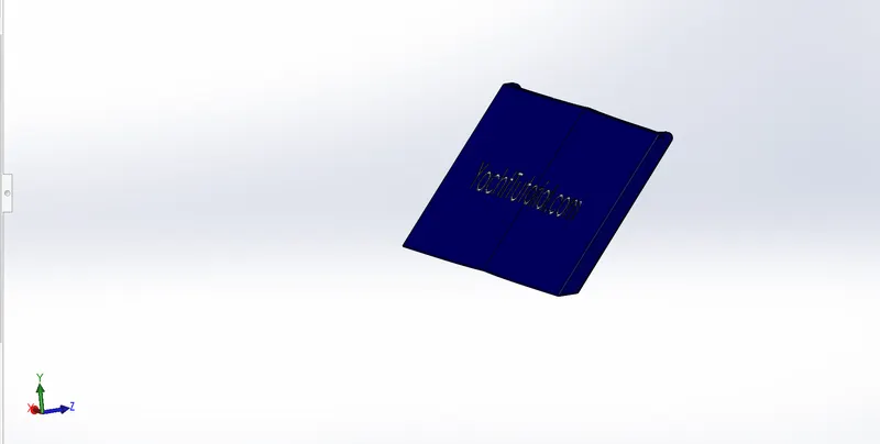
Following commands are used to complete this part :
- Sketch
- Mirror
- plane
- Text
- Shell
Front seat:
Seat are mean to have rest to occupants. Front seat lies exactly in front of superstructure in between of that we small water pool. Front seat designed using surface features and some of solid feature with reference to deck surface. Here we used dome feature to give shape like cushions.
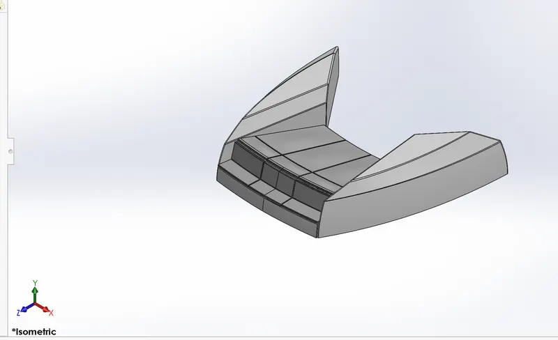
Following commands are used to complete this part :
- Plane
- Sweep
- Surface loft
- Surface trim
- Extrude cut
- Revolve
- Surface knit
- Surface fill
- Dome
- Mirror
- Fillet
- Chamfer
Middle Seat:
Middle seat is situated next to superstructure. It is modelled with reference to deck surface.
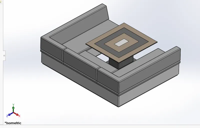
Following commands are used to complete this part :
- sketch
- Extrudeboss
- Chamfer
- Mirror
- Line
- Rectangle
- Offset entities
- Extrude cut
Rear Seat:
Rear seat locate at the end of deck. We used many surface feature to model this seat with reference to deck surface. A flag is modelled with 3D sketch giving a real look to it as it show during wind flow.
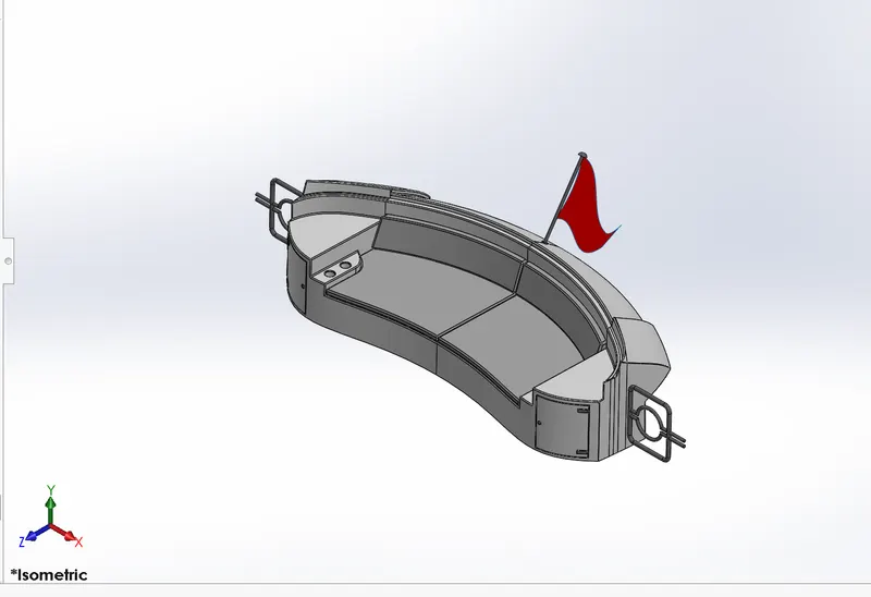
Following commands are used to complete this part :
- Sketch
- Surface extrude
- Surface loft
- Surface offset
- Surface trim
- Sweep
- Ruled surface
- Surface extend
- Extrude boss
- Chamfer
- Extrude cut
- Mirror
- Plane
- Fillet
Superstructure:
It is the extension above deck surface of hull which house accommodation, offices, signal and communication unit, utility space and electrical system which are indispensable to the operation and the functionality of the ship as well as the sustainability of crew.
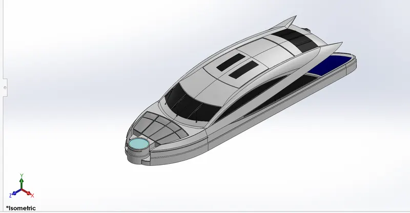
Following commands are used to complete this part :
- Line
- Spline
- Circle
- Extrude cut
- Projected curves
- Offset
- Surface fill
- Surface extrude
- Surface sweep
- Dome
- Surface trim
- Extend surface
- Surface knit
- Plane
- Ruled surfaces
- Split entities
- Deleted faces
- Fillet
- Chamfer
- Mirror
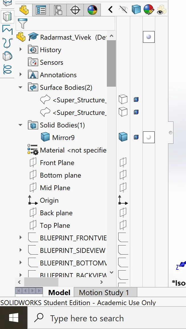
Radar Mast:
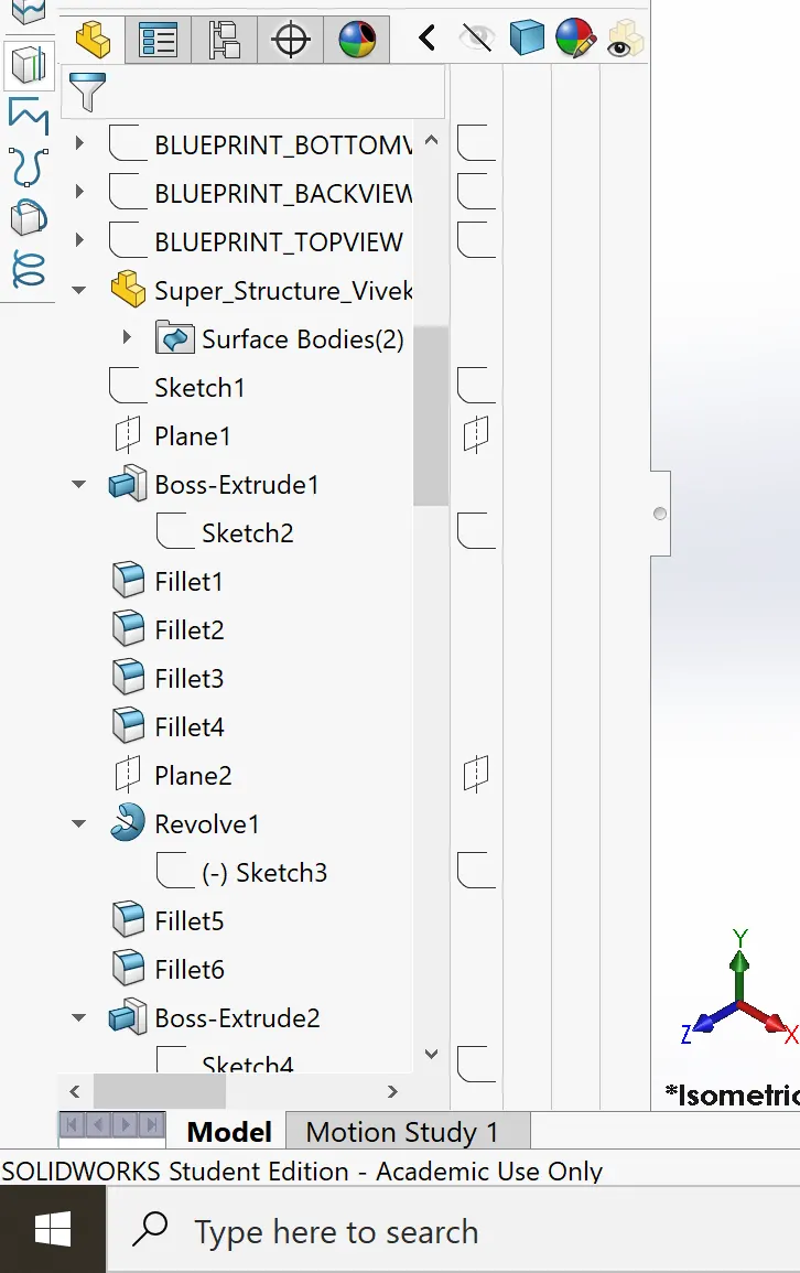
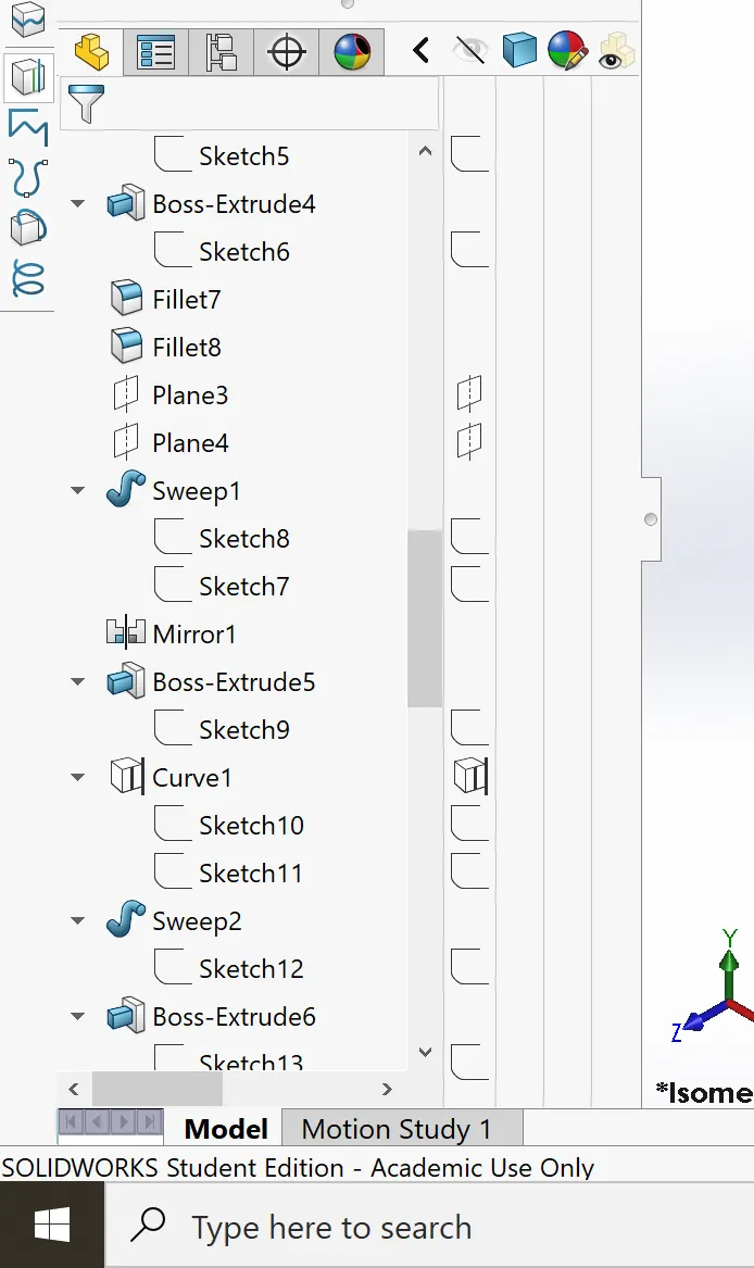
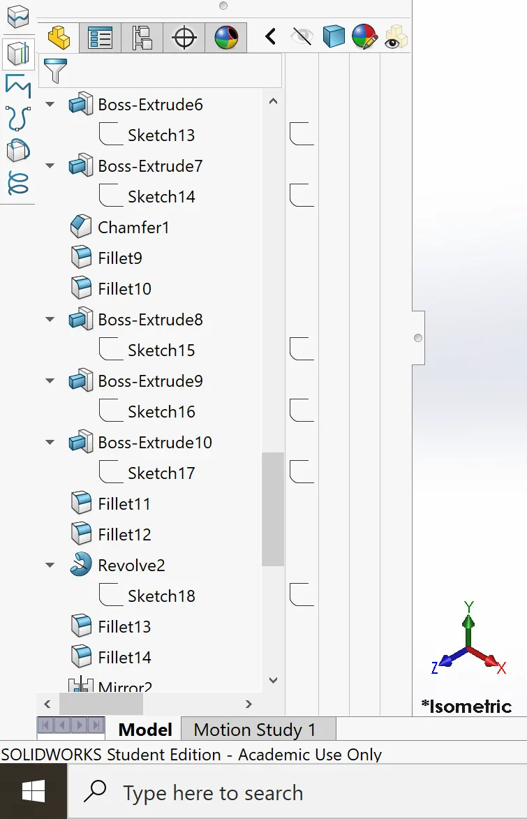
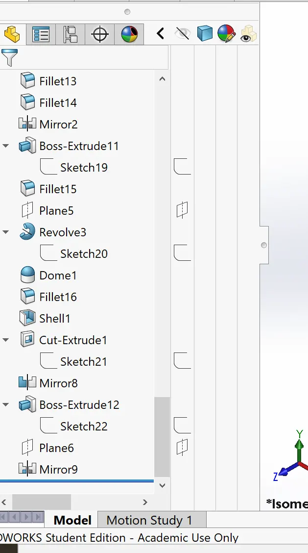
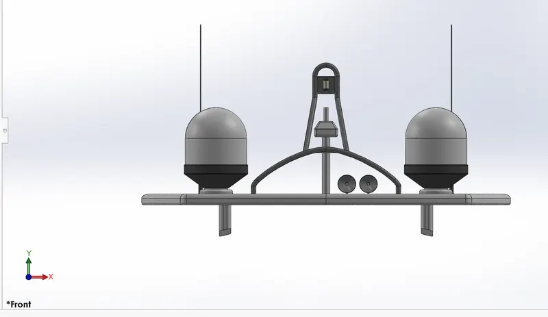
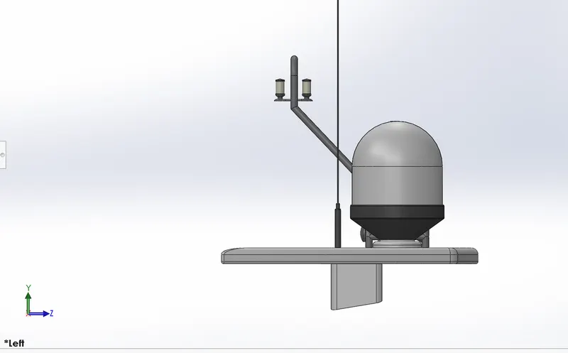
A mast system is composed mainly of supporting frames, a c shape base plate, radar ( transmitter and receiver) and an antenna. This modelled with reference to superstructure top surface. Base plate support all equipment components over it.
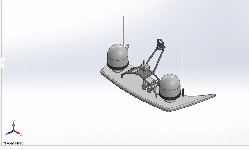
Following commands are used to complete this part :
- Sketch
- Spline
- Extrude boss
- Revolve
- Circle
- Mirror
- Line
- Fillet
- Chamfer
- Shell
- Projected curve
Assembly of Yatch Model :-
Assembling is a process in which individual components of a system are placed together to form a complete system that we be worked as desired. There are mainly two types of approaches in assembly as follow.
- Top Down Approach
In top down parts, location of parts, designed related parameters are done in assembly environment itself. Hence with this approach very less rework required to change in design.
- Bottom Up Approach:
in is the traditional way in which we design parts or components individually and then insert them into assembly environment as needed and apply mates to define relative position each component. If there is any interference in assembly then we have to make changes separate in each part.
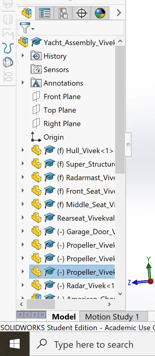
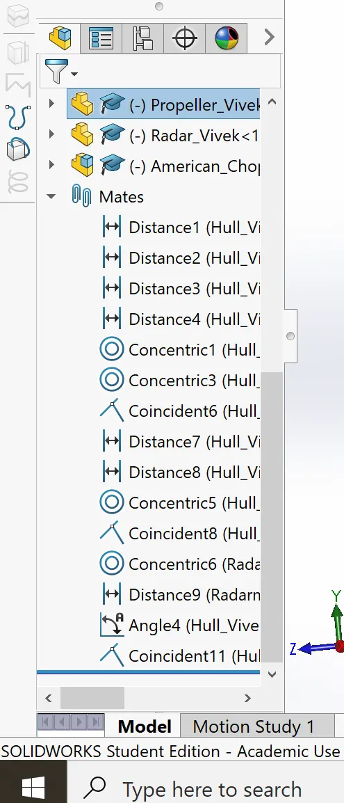
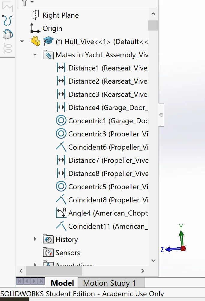
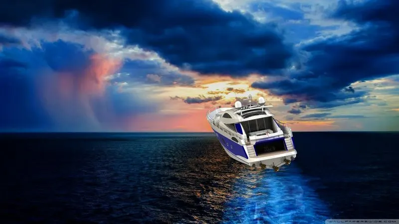
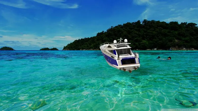
The assembly of yatch is quite simple since wehave taken the base deck surface for the most of the parts it gets mated automatically although some mates are used to assemble the yatch.
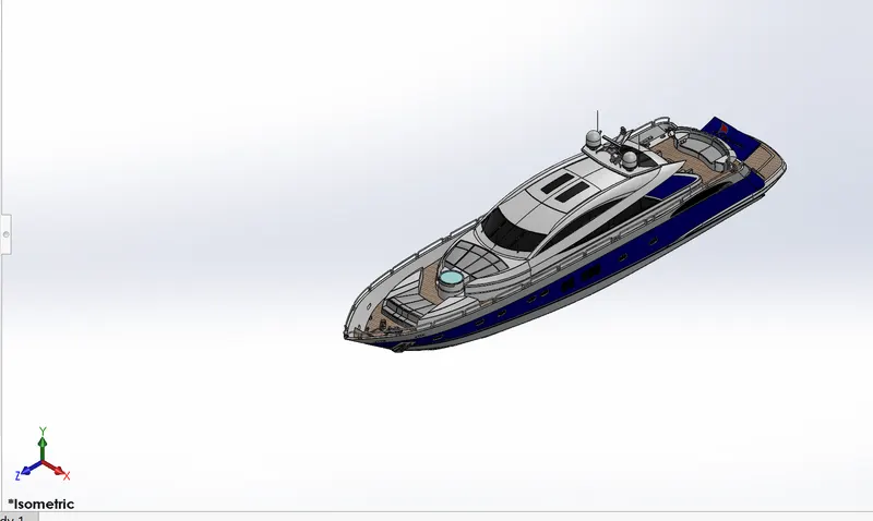
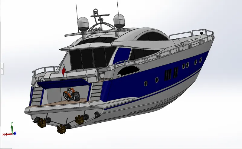
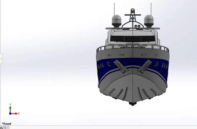
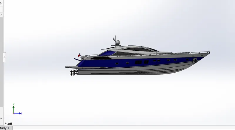
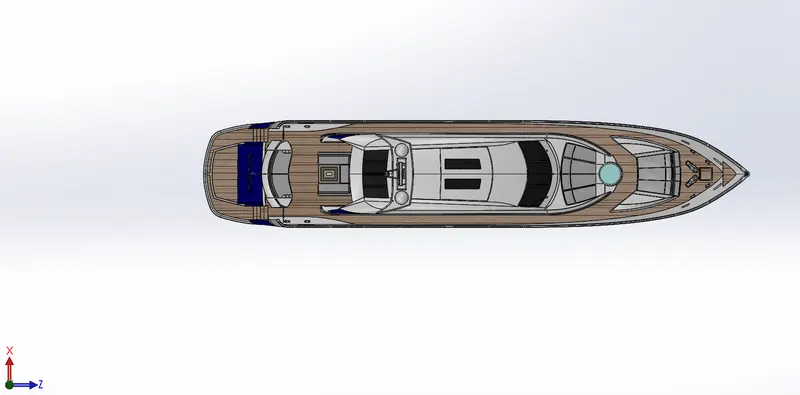
Rendering using photoview 360
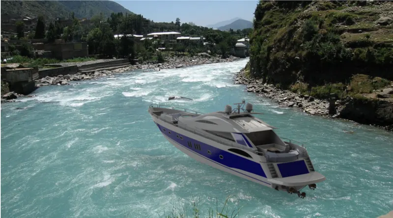
PhotoView 360 is a SOLIDWORKS add-in that produces photo-realistic renderings of SOLIDWORKS models. The rendered image incorporates the appearances, lighting, scene, and decals included with the model. PhotoView 360 is available with SOLIDWORKS Professional or SOLIDWORKS Premium.
- With a model open, click Tools > Add-In and add in PhotoView 360.
- Start a preview in the graphics area or open thepreviewwindow to see how changes you make to the model affect the rendering.
- Edit appearance, the scene , and decals.
- Edit lights
By default, lighting is off in PhotoView. With lights off, you can use the realistic lighting provided by scenes, which is usually sufficient for rendering. You typically need additional lighting in PhotoView to illuminate occluded spaces in the model.
- Edit photoview options
- When you are ready, perform a final render either now (PhotoView > Final Render ) or later ( PhotoView > Schedule Render ).
If annotations or dimensions are visible in your model, a dialog box appears with options to include the dimensions and annotations or render without them.
If you have not added a camera or turned on perspective view, which provide more realistic, higher quality renderings, a dialog box appears. You can turn on a camera or perspective view from the dialog box or continue without them.
- Make detailed adjustments in thefinal render window
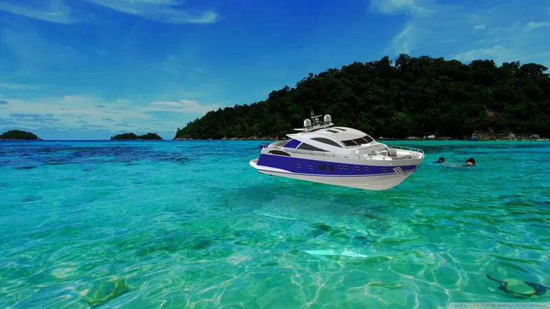
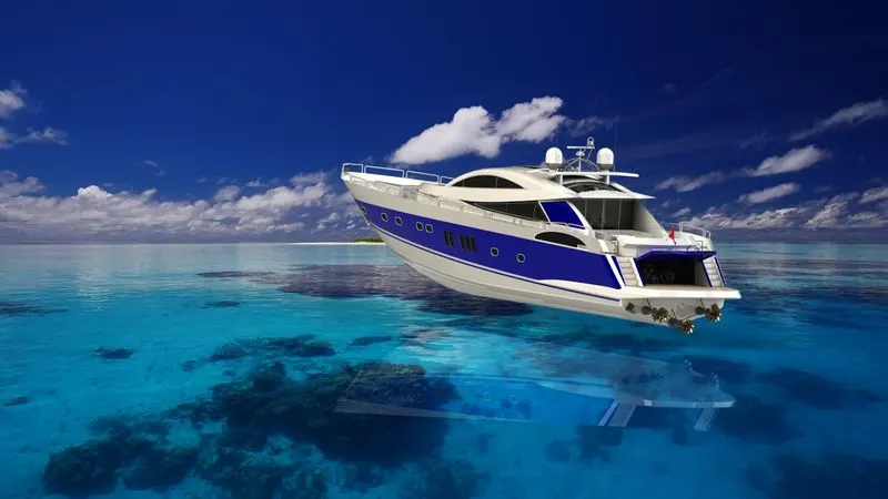
Conclusion :
- Learnt to use surface modelling feature and converting them to solid model.
- Design of complex shape and feature with applying appropriate appearance.
THANK YOU
RADARMAST & YACHT FEATURE TREE :-