Week-7 Challenge: DC Motor Control
Q1 : A) Explain a MATLAB demo model named 'Speed control of a DC motor using BJT H-bridge'.
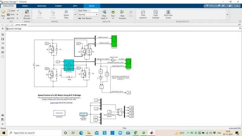
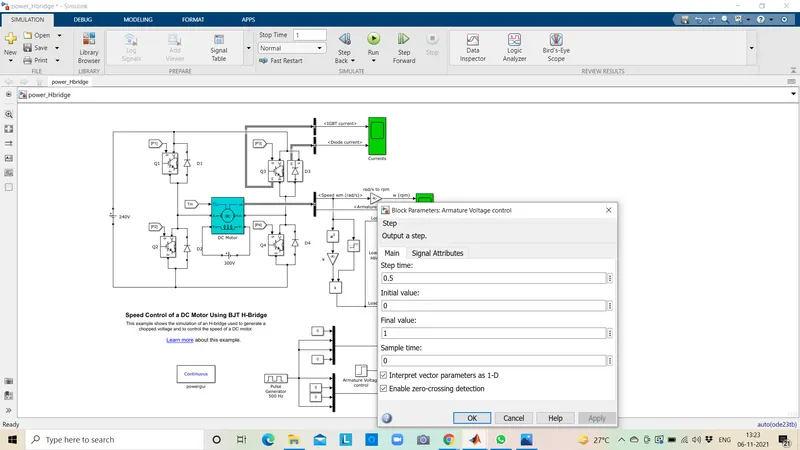
- This image shoes the voltage value given from initial to final during the step time.According to the pulses on and off the voltage supplied to the IGBTs
- Here four switches are used Q1,02,03,04. Pulses P1,P2,P3,P4 are conected with corresponding switches.
- In first state, Q1 and Q4 are closed by giving 1V to IGBT'S,current from battery passes through Q1 and Q4.Diode D2,D3 are used as free wheeling diode in this state.ln this case Forward motoring and forward breaking are held.
- In Second state,02 and Q3 are closed by giving 1V to IGBT's,current from battery passes through Q2 and 03.Diode D1,D4 are used as free wheeling diode in this stateln this case reverse motoring and reverse breaking are held.The current direction change its direction in this state.
- Both the states are occuring in O.5 seconds in their sample time.Thus DC supply converted and feeded to the armature of the motor.
- Here free wheeling diodes are used as a safety purpose of this inverter Circuit as when the flow of current on low values protects the circuit and machine by feed backing the current or in high voltage fluctuvations voltage get splited as protection to the motor and circuit components.
- In motor operation, armature terminals are connected with a 240V along the inverter circuit and field windings are connected with 300 V DC suppy to act as a electro magnet for the motor.
- The load torque is given as mechanicalinput to the motor for its referance.
- Thus through this magnetic fields generated, variable current arring conductors in rotor armature produces forces according to fleming left hand rule principle. Thus the motor starts to rotate.
- Here run this demo model and study the results from scopes.
Result :
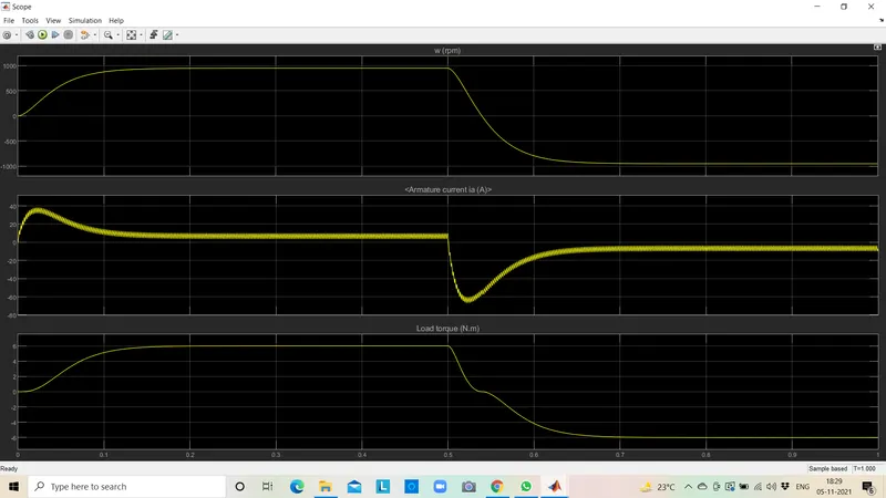
From the result scope we are getting,
Speed of motor:
- Initially increases to O to nearly 900 rpm upto O.5 secs(Forward motoring action takes place).
- Then speed reduces to O rpm(Forward dynamic breaking action takes place).
- Then speed increases from O to -900 rpm at upto 1 sec( Reverse motoring action takes place).
- Then reverse dynasmic breaking occurs(Not shown in scope).
Load torque of motor :
- Initially torque increase from O to 0.5 secs in forward motoring action.
- Then torque reduces to O Nm in forward dynamic breaking mode.
- Then torque increases in reverse direction in reverse motoring action upto 1 sec.
- Again torque reduce to zero.(Not shown in scope)
B) Armature current shoot up in motor.
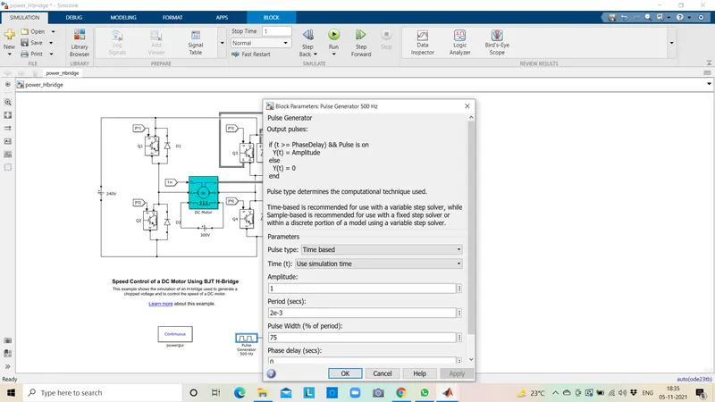
Here the initial current shoot up is due to sudden increase in voltage which inurns regulated by duty cycle.In this case motor driven in 75% of duty cycle.i.e)
0.75*240= 180 V.
We can change the duty cycle to 50%(120 V) and seen the results as,
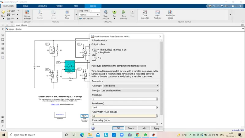
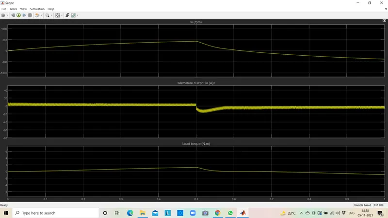
Sudden shoot up canceled in starting condition but slight shootup after 0.5 sec in reverse motoring condition.
Again changing duty cycle to say 25%, we get the result as,
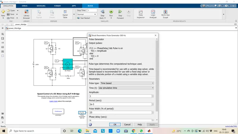
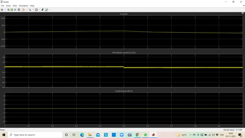
The shoot up of current get dimlished on both ends.
Conclusion : Thus to reduce the shoot up armature current we have to change the duty cycle gradually from 0 to 100%, that inturns increases voltage gradually and speed also changes accordingly.
C) Refer to the help section of 'The Four-Quadrant Chopper DC Drive (DC7) block'. Comparing it with the H-bridge model.
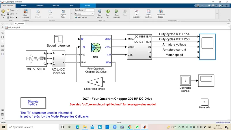
The 200 HP DC motor is separately excited with a constant 15O V DC field voltage source. The armature voltage is provided by an IGBT converter controlled by two Pl regulators. The converter is fed by a 515 V DC bus obtained by rectification of a 380V AC 50 Hz voltage source. In order to limit the DC bus voltage during dynamic braking mode, a braking chopper has been added between the diode rectifier and the DC7 block.
The first regulator is a speed regulator, followed by a current regulator. The speed regulator outputs the armature current reference (in p.u.) used by the current controller in order to obtain the electromagnetic torque needed to reach the desired speed. The speed reference change rate follows acceleration and deceleration ramps in order to avoid sudden reterence changes that could cause armature over-current and destabilize the systenm. The current regulator controls the armature current by computing the appropriate duty ratios of the 5 kHz pulses of the four IGBT devices (Pulse Width Modulation). For proper system behaviour, the instantaneous pulse values of IGBT devices 1 and 4 are opposite to those of IGBT devices 2 and 3. This generates the average armature voltage needed to obtain the desired armature Current. In order to limit the amplitude of the urrent oscillatioms., a smoothing inductance is placed in series with the armature circuit.
Simulation :
Before starting the simulation, set the initial bus voltage to 515 V via the GUI block (The Initial States Setting' button and 'Cbus' variable).
Start the simulation. You can observe the motor armature voltage and current, the four IGBT pulses and the motor speed on the scope. The current and speed references are also shown.
The motor is coupled to a linear load, which means that the mechanical torque of the load is proportional to the speed.
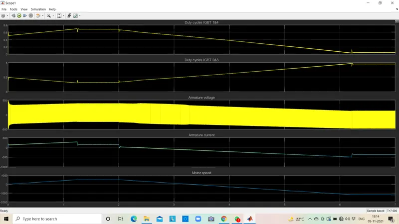
The speed reference is set at 500 rpm at t O s. Observe that the motor speed follows the reference ramp accurately 400 rpm/s) and reaches steady-state around t= 1.3 s.
The armature current follows the current reference very well, with fast response time and small ripples. Notice that the current ripple frequency is 5 kHz.
At t= 2 s, speed reference drops to -1184 rpm. The current reference decreases to reduce the electromagnetic torque and causes the motor to decelerate with the help of the load torque
At t= 2.2 s, the current reverses in order to produce a braking electromagnetic torque dynamic braking mode). This causes the DC bus voltage to increase.
At t= 3.25 s, the motor reaches O rpm and the load torque reverses and becomes negative. The negative current now produces an accelerating electromagnetic torque to allow the motor to follow the negative speed ramp 400 rpm/s).
At t = 6.3 s, the speed reaches 1184 rpm and stabilizes around its reference.
Scope Result :
Four Quandrant Chopper :
- It converts electrical energy to mechanical energy which supports its motion. In braking, it works
as a generator converting mechanical energy to electrical energy and opposes the motion. - The motor can be providing motoring and braking operating for both forward and reverse direction.
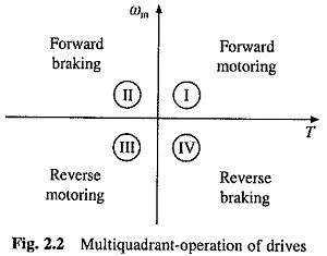
- The torque and speed coordinates for both forward and reverse motions are.
- Power developed by a motor is given by the product of speed and torque.
- In Quadrant 1st developed power is the +ve and called forward motoring mode.
- In Quadrant 2nd developed power is -ve hence machine works under braking opposing the motion and this is knowns as forward braking mode.
- Similarly, Quadrant 3rd known as reverse motoring.
- Quadrant 4th known as reverse braking.
Comparison of Four-Quadrant chopper DC7 block and H-bridge model:
| S.no | Four-Quadrant Chopper DC Drive (DC7) block | H-bridge model |
| 1 | Generally used in Automative for controlling DC motor speed and direction. | It is generally used in Robotics & Electro-mechanical devices for controlling the DC motor speed and direction. |
| 2 | Regenerative braking is possible in DC7. | Dynamic braking is only posible. |
| 3 | It can operate in all 4 quadrants of DC motors. | It can only operate only in forward and reverse directions. |
| 4 | Only DC-DC converters high switching frequency is possible. | It shows the simulation value in accurate mode. |
| 5 | It has a wider range of torque and output power. | It has a narrow torque and output power. |
Q2 : Develop a 2-Quadrant Chopper using Simulink & explain the working of the same with the relevent results.
Two Quadrant Type-A or Type-C
- Class-C Chopper is a Two Quadrant Chopper.
- It Function in 1st and 2nd
- In Class C Chopper, Output Voltage is always positive and output current can be Positive or Negative.
- This type of Chopper obtained by connecting Cass-A and Class-B chopper in Parallel.
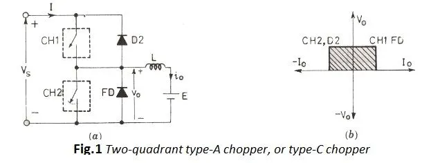
Where,
Vs = DC Voltage Source.
CH1 = Power electronic switch 1.
CH2 = Power electronic switch 2.
D2,FD = Free wheeling diodes.
L = Inductor load.
E Back EMF from load.
Working :
- The sequence of Gatel current (lg1) and Gate2current (lg2) show how we Trigger CH1 with Ig1 and CH2 with lg2 current.
- As seen in above fig 1st we Trigger lg1 means CH1 switch will dose and current will flow from Vs to CH1 to Inductor(L) to E to Back to Vs while this process Inductor(L) will get Charge by (+ -) Polarity.
- Direction of current can be seen positively increasing .
- After Ig1 is OFF current will flow by reversing the Direction of Inductor as inductor is discharging by reversing its Polarity to (- ) which will be conducting Diode D2 in (Decreasing For Short time as per Inductor capacity)
- Now after once we Switch on CH2 as per lg2 triggering seen above, we see that EMF is Charging Inductor with Polarity (-) from E to L to CH2 to back to E in Loop (current from Vs is OFF as its terminal CH1 is open and Diode D1 is in Reverse bias ).,
- EFM is supply Charge in Loop so Current will be Negatively Increasing during Switch CH2.
- Once Switch is Close at that time period Diode D1 will Conduct by Reversing Polarity to (+-) of Inductor(L) now Current can be Seen in LOOP (E to Inductor to Diode D1 to Vs) there by allowing Vs to supply Current to circuit.Current is Negative, as D1 act as Forward bias now it will be increasing till zero and further Cycle Continuous by keeping on repeating.
- Charging of Inductor (L) which tends to changing it Polarity is the Game Changer in the Circuit.
- When CH1is ON supply voltage will appear at Output Voltage and when Diode D1 is ON supply appear to output voltage is Vs, SO the Supply Voltage VS will be appearing while CH1 ON and Diode DI ON in OUTPUT.
Conclusion :
- Average Output Voltage of Class Chopper is Positive and Average Output Current of Class C Chopper can be Positive or negitive (Depending on which Switch is ON).
- When Chopper CH1 or D2 Diode Conducts,Load current is Positive.
- When Chopper CH1 or D1 Diode Conducts,Loadd current is Negative.
- CH1 and CH2 should not Trigger Simuntaneously, Else DC supply Source will get Short Circuit.
- Class C Chopper can be used both for DC Motor control and Regenerative Braking of DC Motor.
Simulink Model :
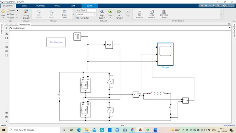
Explanation of Model Construction :
- Click on Simulink Browser and open Library to Search for Componant required to Build C-Class chopper as Follows:
- POWER GUI : Without this Block Simulation will not take place.
- Voltage Measurement Block.
- Current Measurent Block.
- DC Voltage Source : Chose Black which are use for power electronic application.
- MOSFET.
- Pulse Generator.
- Diode.
- Series RLC Band.
- Logical Operator : For Simultaneous Switching NOTGATE.
- Arrange the Blocks as per circuit connection shown above in Model.
- Double Click on MOSFET and DIODE Block to Disable (uptick show measurement port), and rotate the DIODE in upward direction as per our requirement ( source should be facing in downward direction for MOSFET and for DIODE source should be in upward direction.
- Open series RLC band block and Change the branch type to (L) with default value 1 mill H, once done arrange according to circuit diagram.
- Open logical operator and select NOT in Operation options, connects its Input to output of PULSE Generator block. The reason we use NOT gate to ensure both the Switches does not conduct simultaneously if they do so supply will be short-circuited.
- We will be giving the tapping for the PULSE gate terminal for 1 switch CH1 and from NOT gate we are giving it to other switch CH2. So if CH1 is conductingg CH2 will not conduct because we are using the NOT gate.
- Once done we will be measuring the voltage by connecting its 1 port at staring of inductor and other to DC2 supply which is connected adjacent.
- And output is connect to 1st of the 3 port of scope input, current Measurement port is also connected to 2nd port of Scope and 3 ports taken from output of PULSE Generator.
- Double click on main DC Voltage supply and set amplitude (V) to 24v and for adjacent DC2 supply set amplitude as 12v.
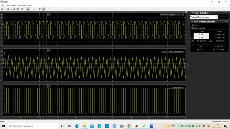
- Open Pulse generator block set amplitude to 10 for better viewing, time period set to O.02 sec, pulse width is 50 (because we 50 % to be ON and 50% to be OFF) .i.e. NOT gate is ON when 50% OFF.
- Now set the simulation time for 1 sec and RUN the simulation.
OUTPUT Results :
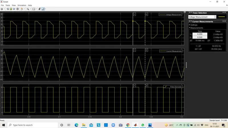
ZOOMING Same Results :
Q3 : Explain in a brief about operation of BLDC motor.
Brushless DC motor have been a much focused area for numerous motor manufacturers as these motors are increasingly the preferred choice in many applications, especially in the field of motor control technology. BLDC motors are superior to brushed DC motors in many ways, such as ability to operate at high speeds, high efficiency, and better heat dissipation.
They are an indispensable part of modern drive technology, most commonly employed for actuating drives, machine tools, electric propulsion, robotics, computer peripherals and also for electrical power generation. With the development of sensorless technology besides digital control, these motors become so effective in terms of total system cost, size and reliability.
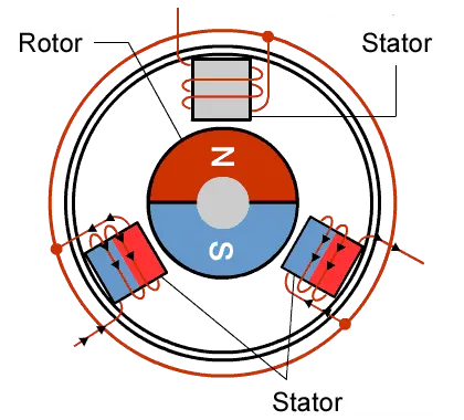
As their name implies, brushless DC motors do not use brushes.
With brushed motors, the brushes deliver current through the commutator into the coils on the rotor.
So how does a brushless motor pass current to the rotor coils?
It doesn't-because the coils are not located on the rotor. Instead, the rotor is a permanent magnet.
the coils do not rotate but are instead fixed in place on the stator. Because the coils do not move,
there is no need for brushes anda commutator.(see figure)
With the brushed motor, rotation is achieved by controlling the magnetic fields generated by the coils on the rotor, while the magnetic field generated by the stationary magnets endures fixed.
To change the rotation speed, you change the voltage for the coils. With a BLDC motor, it is the permanent magnet that rotates.
Rotation is achieved by changing the direction of the magnetic fields generated by the enclosing stationary coils.
To control the rotation, you change the magnitude and direction of the current into certain coils.