Week-7 Challenge: DC Motor Control
1. A. Explain a MATLAB demo model named ‘Speed control of a DC motor using BJT H-bridge’.
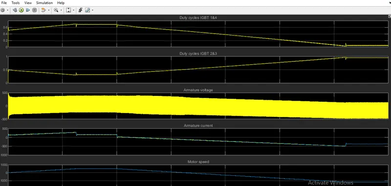
B. Comment on the armature current shoot-up from the scope results.
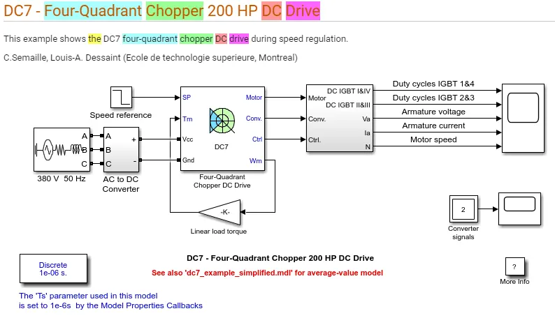
C. Refer to the help section of ‘The Four-Quadrant Chopper DC Drive (DC7) block’. Compare it with the H-bridge model.
2. Develop a 2-quadrant chopper using simulink & explain the working of the same with the relevant results. (Refer to article - Multiquadrant operation of motor )
3. Explain in a brief about operation of BLDC motor.
ans- 1-BJT H bridge is used to generate chopped voltage and to control speed of dc motor. Bi polar junction transfer is used as switch like IGBT. IT IS CONTROLLED BY SIMULINK SIGNAL.dc motor uses preset model. it simulate a fan type model.load torque is proportional to square of speed. armature voltage is from 0 to 240 v.
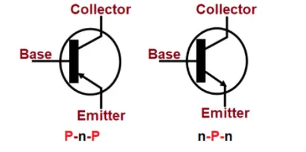
BJT(BIPOLAR JUNCTION TRANSISTOR)- IT IS a 3 terminal semiconductor device.it uses ptype and ntype semiconductor device in which current flow.it contain silicon and impurities are added to via doping.in p type electons are attracted and ntype electons are go to out side. it ensure carge can not retain in direction which comes.
bjt is ptype and ntype three layer sandwitch.1. base inwhich small starting current is attached. 2.emittor which emits electrons. 3.collector which collects electron which are further amplified.electrons are passed from emittor to base.
they can operate within 3 region. 1.active region-transistor operate as amplifier. 2.transistor is fully on and act as switch. 3.cutoff -transistor is fully off. they are NPN and PNP type.
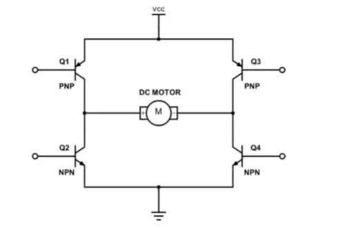
BJT H BRIDGE HAVE FULL CONTROL OF DC MOTOR. it allows a microcontroller ,logic chip and remote control to electronic controlto go forward ,reverse brake, and coast. it consists 4 bjt diode pairs. two transistor switsched parallely.
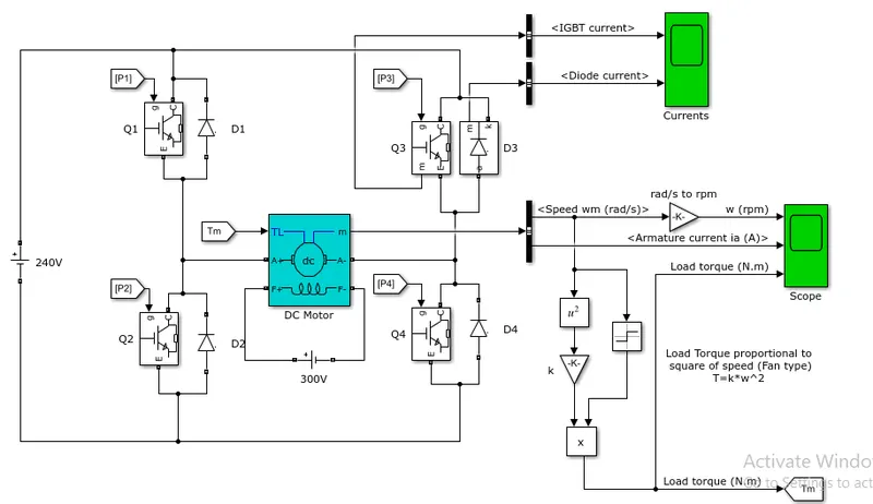
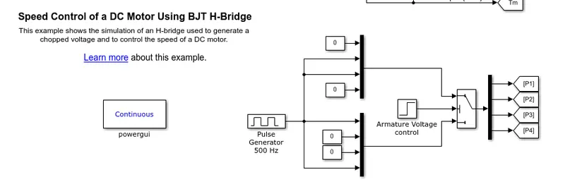
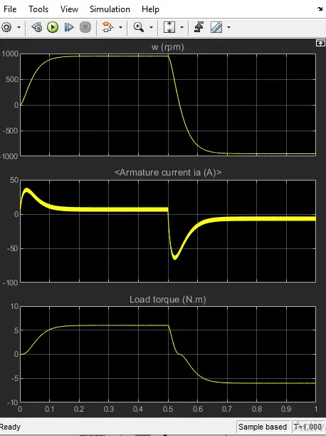
motor starts with aduty cycle of 75%. at 0.5 sec armature voltage is reversed.and motor run in negative direction.
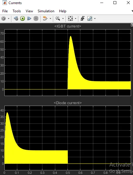
scope show motor sped,armature current and load and currents.
this rogramme is on for 0.75 sec and off by 0.25sec.IGBT signal is present for 0.5 dec.
0.5 sec diode current is passed and 0.5 sec no current is passed.
motor takes 0.1 sec to reach maximum speed. Q3 MODE MOTOR START REDUCING AND REVERSED.
in chopper duty cycle is 50%.
2. these choppers operates in first and second quadrantmeans souce to load or load to source.we connect both the switches in parallel.
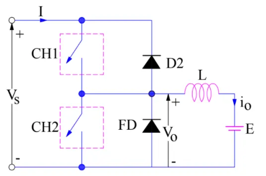
for first quadrant switch ch1 is on and for second quadrant switch ch2 is on.for first quadrant vs is connected to cload so load voltage is equal to source voltage.when ch1 is off vo becomes zero so io mcontinue to die down. so vo and io are positive.
for second quadrant ch2 is switched on ,load dc drive through so io is reversed and current is negative.
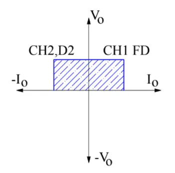
both ch1 and ch2 shoud not be on simultaneouslyto prvent short circuit.
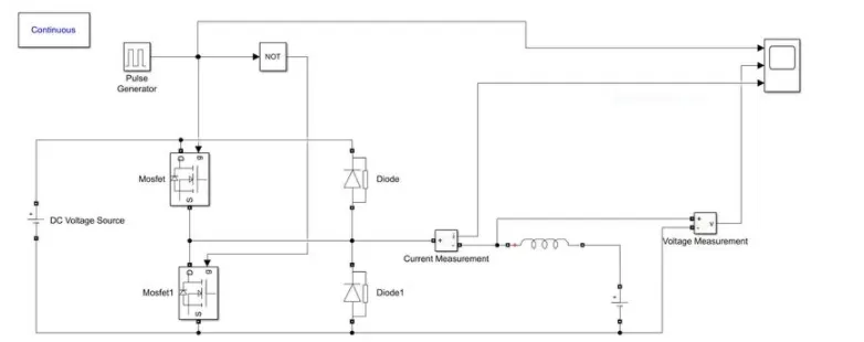
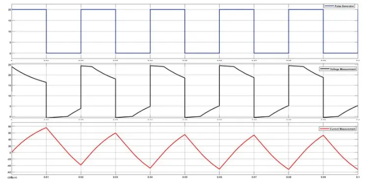
simulink output
3. they are known as electronically commuted motors.rotor is sole bearer of magnet. it does not require any power.motor has control circuitary.motor employs controls ,hall sensor and rotary encoder.
rotar has magnets and stator has current carrying conductors. they use electrically commutator to convet electrical energy into mechanical energy.it has electical commutator with switch circuit. magnetic field generated by stator and rotor runs with same frequency. field is switched to an amplifier.
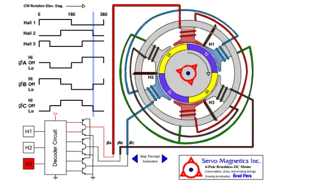
when stator coils gets suplly from sorce electromagmetic field produced. switching makes ac voltage with tyrapzoidal waveform. due to force of interaction between roror and stator rotor continueosly rotates. permanent magnet in rotor align with stator.