Week - 4
- Implement control logic of a “washing machine” using Stateflow as per given sequence:
- If the power supply is available, the system gets activated
- If the Water supply is not available, stop the process & indicate through LED
- Soaking time should be 200s followed by Washing time of 100s.
- Then rinsing happens for next 20s & dryer runs for 50s
After all the processes have completed turn on the finished LED
ans-1.start simulink model & create blank model.
2. using chart block defining condition which is given.
3.control logic for washing soaking and drying is defined.
4. after completing control logic we run programme for 500 seconds.
block used;
1.chart- it is finite element system which is driven by events.
2, rocker switch-for on/off system & connect it to power switch.
3. constant- to define input value.
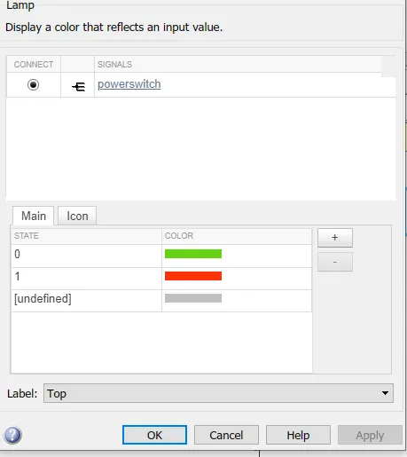
4. lamp-lamp is showing with color that process is completed or not.
5. display-at particular instance it show the output value,
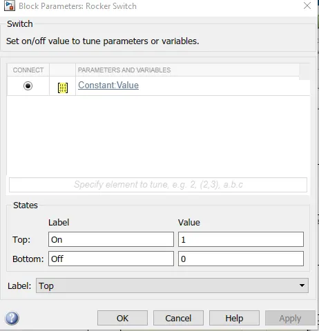
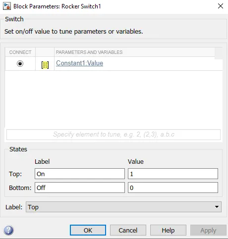
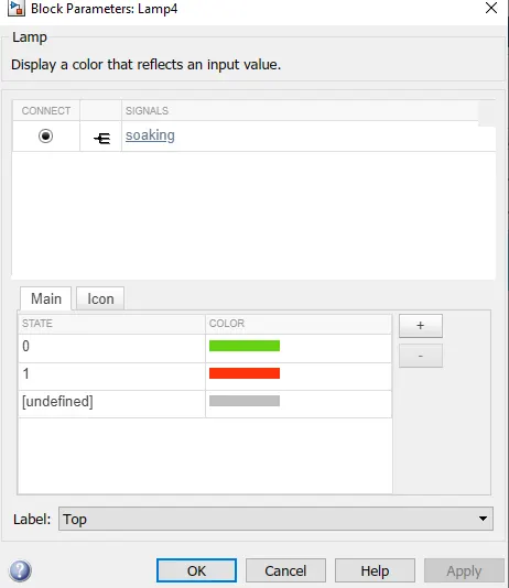
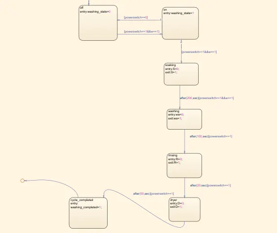
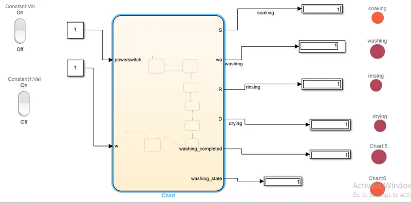
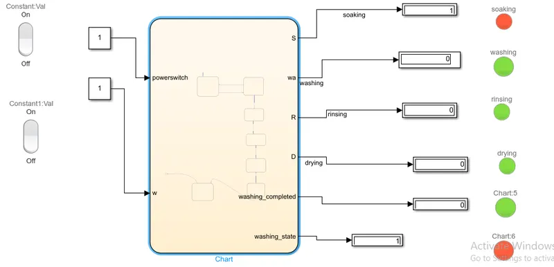
in above logic there are two condition for power supply & water supply.1 for on & 0 for off for 1 process continues & for 0 process is off.for washing,soaking,rinsing & drying we define given time. & lamp are defined which process is doing whichprocess is completed we difine color for it.
2. Make a Simulink chart for the “Gear shift” logic as per below conditions:
Speed Range(kmph) Gear
0 to 15 1
16 to 25 2
26 to 40 3
41 to 60 4
Above 61 5
Give speed input while the simulation is running & display the gear number.
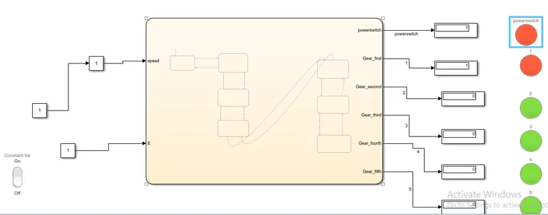
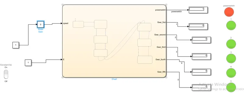
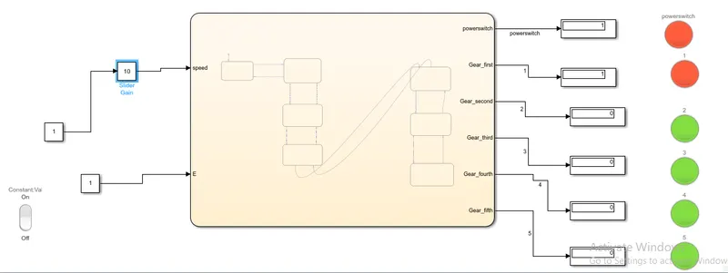
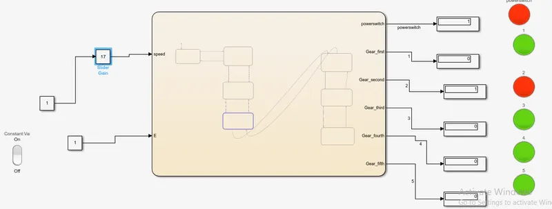
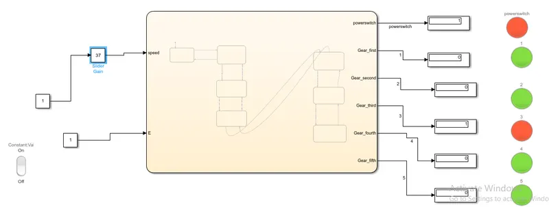
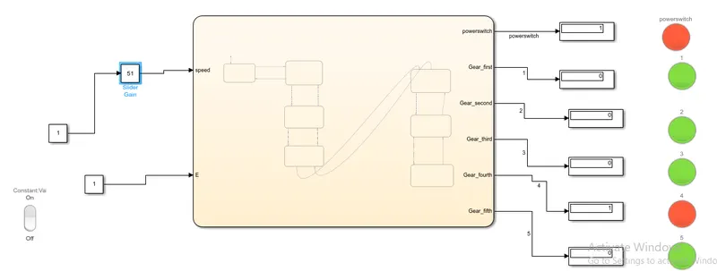
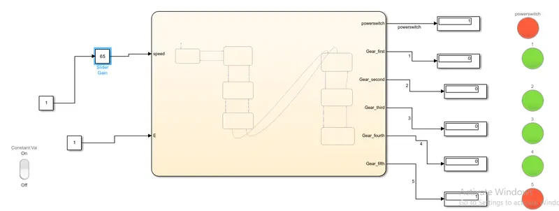
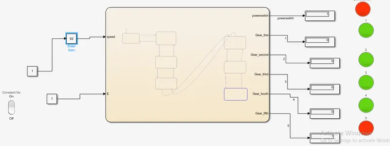
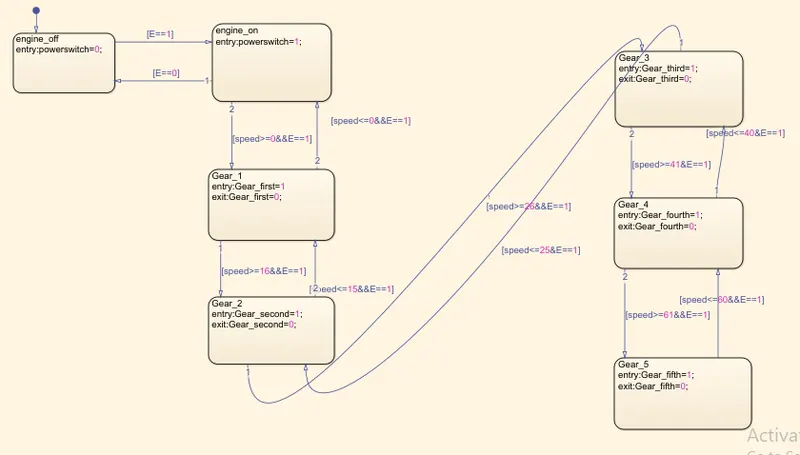
ans-we create simulink model for stateflow.& define control logic as speed changes gear shift automatically.
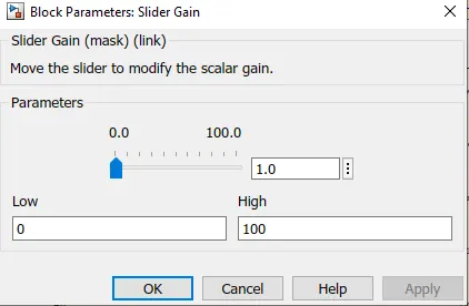
we run simulation for infinite time & stop any instance to see the condition.we use as input rocker switch slider gain(to vary speed from 0 to 100),constant to show on/off.for output we use power switch gear1,gear 2,gear3,gear 4,gear 5.
&displays & lamps.
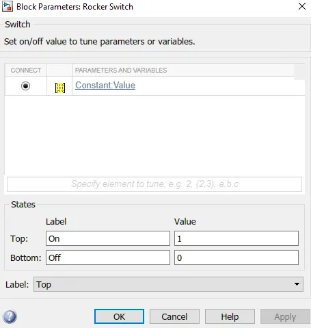
control logic
lamp