DC Motor Control
1. A. Explain a MATLAB demo model named ‘Speed control of a DC motor using BJT H-bridge’.
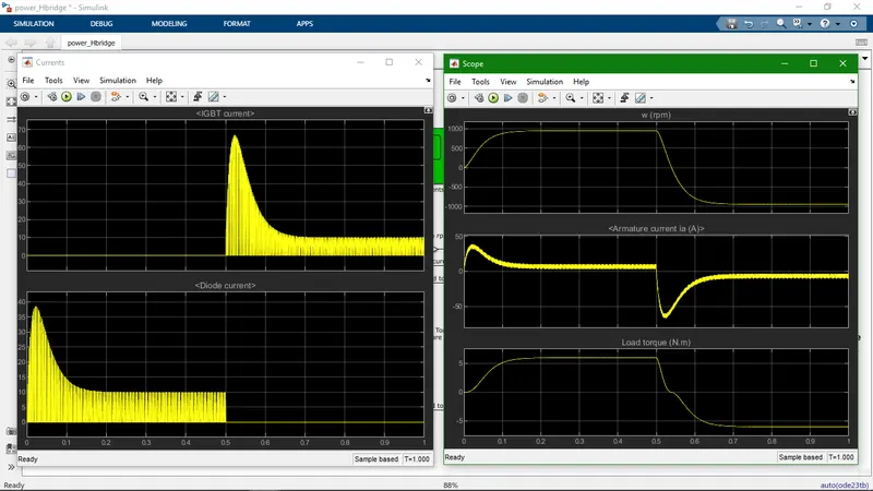
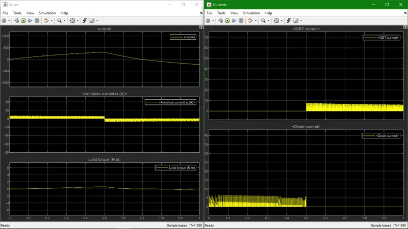
B. Comment on the armature current shoot-up from the scope results.
C. Refer to the help section of ‘The Four-Quadrant Chopper DC Drive (DC7) block’. Compare it with the H-bridge model.
A. Explain a MATLAB demo model named ‘Speed control of a DC motor using BJT H-bridge’.
Answer 1 - A.
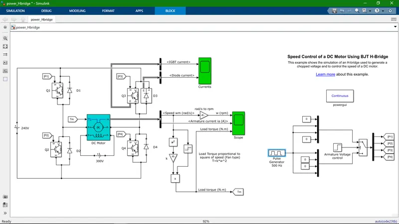
- The simulation of an H-bridge used to generate a chopped voltage and to control the speed of a DC motor.
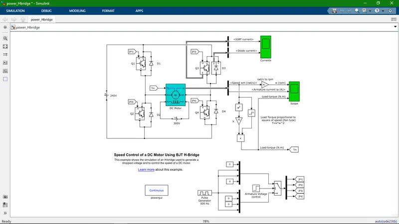
Speed Control of a DC Motor Using BJT H-Bridge
The Bipolar Junction Transistor (BJT) when used for power switching applications, operates as an IGBT. When it is conducting (BJT operating in the saturated region), a forward voltage Vf is developed between collector and emitter (in the range of 1 V). Therefore, the IGBT block can be used to model the BJT device.
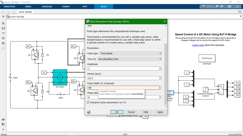
The IGBT block does not simulate the gate current controlling the BJT or IGBT. The switch is controlled by a Simulink® signal (1/0). The DC motor uses the preset model (5 HP 24V 1750 rpm). It simulates a fan type load (where Load torque is proportional to square of speed). The armature mean voltage can be varied from 0 to 240 V when the duty cycle (specified in the Pulse Generator block) is varied from 0 to 100%.
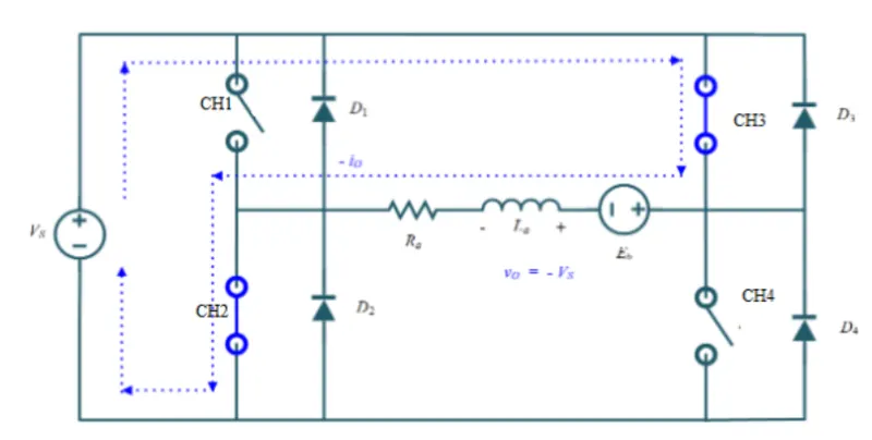
The H-bridge consists of four BJT/Diode pairs (BJT simulated by IGBT models). Two transistors are switched simultaneously: Q1 and Q4 or Q2 and Q3. When Q1 and Q4 are fired, a positive voltage is applied to the motor and diodes D2-D3 operate as free-wheeling diodes when Q1 and Q4 are switched off. When Q2 and Q3 are fired, a negative voltage is applied to the motor and diodes D1-D4 operate as free-wheeling diodes when Q2 and Q3 are switched off.
- Motor rotation direction is forward when switch no.1 and 4 is on there for motor rotates in clockwise direction.
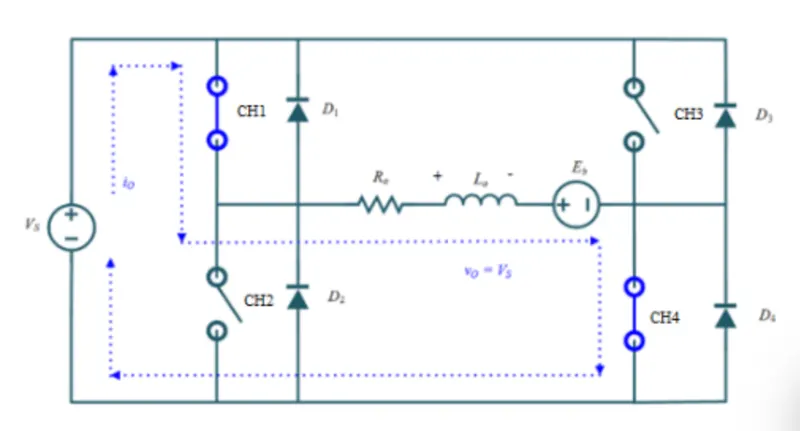
- Switch no.3 and 2 is in operating condition at that time the motor rotates in anticlockwise direction.
B. Comment on the armature current shoot-up from the scope results.
Answer 1 - B.
C. Refer to the help section of ‘The Four-Quadrant Chopper DC Drive (DC7) block’. Compare it with the H-bridge model.
Answer 1 - C.
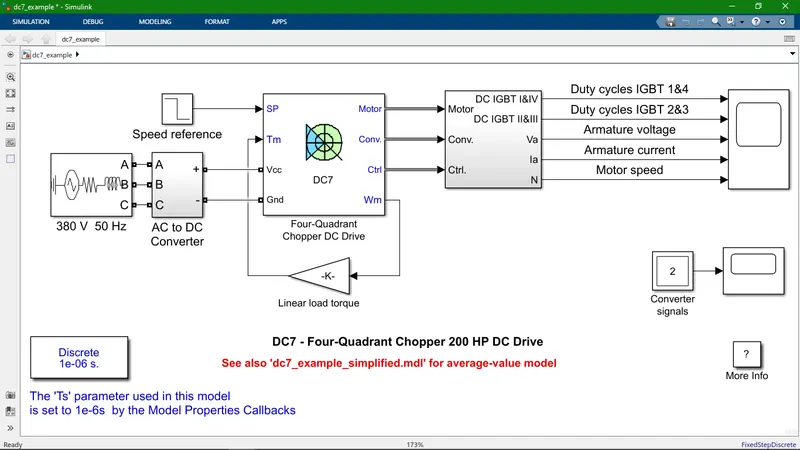
DC7 - Four-Quadrant Chopper 200 HP DC Drive
The 200 HP DC motor is separately excited with a constant 150 V DC field voltage source. The armature voltage is provided by an IGBT converter controlled by two PI regulators. The converter is fed by a 515 V DC bus obtained by rectification of a 380 V AC 50 Hz voltage source. In order to limit the DC bus voltage during dynamic braking mode, a braking chopper has been added between the diode rectifier and the DC7 block.
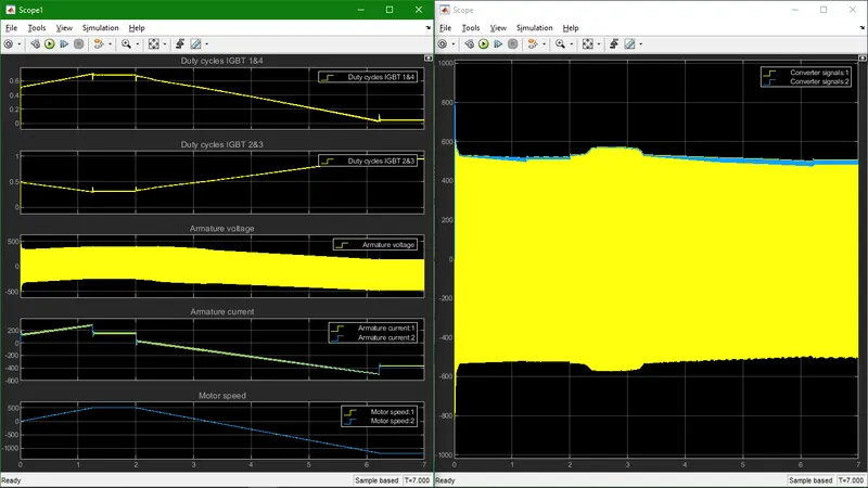
The first regulator is a speed regulator, followed by a current regulator. The speed regulator outputs the armature current reference (in p.u.) used by the current controller in order to obtain the electromagnetic torque needed to reach the desired speed. The speed reference change rate follows acceleration and deceleration ramps in order to avoid sudden reference changes that could cause armature over-current and destabilize the system. The current regulator controls the armature current by computing the appropriate duty ratios of the 5 kHz pulses of the four IGBT devices (Pulse Width Modulation). For proper system behaviour, the instantaneous pulse values of IGBT devices 1 and 4 are opposite to those of IGBT devices 2 and 3. This generates the average armature voltage needed to obtain the desired armature current. In order to limit the amplitude of the current oscillations, a smoothing inductance is placed in series with the armature circuit.
- Operation of four quadrant chopper (consider above-mentioned circuit diagram).
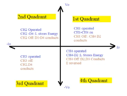
- Compare between The Four-Quadrant Chopper DC Drive (DC7) block and the H-bridge model
| Sr. No. | 4 Quadrant Chopper DC7 | H-bridge model (2 Quadrant) |
| 1. | In this cricuit give 4 different outputs. | In this cricuit give 2 different outputs. |
| 2. | More controlling in terms of braking. | Less control (Only forword and reverse) |
| 3. | Cricuit is Separately excited. | Cricuit is Not separately excited. |
| 4. | In this cricuit two PI regulators | In this cricuit no PI regulators used. |
| 5. | Input power supply is AC and use AC to DC Convertor. | Here input power supply is DC. |
| 6. | Use (regenerative)dynamic brake system for produce power. | This system not capable to produce power by using regenerative brake system. |
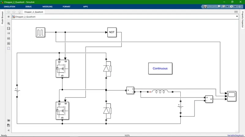
2. Develop a 2-quadrant chopper using simulink & explain the working of the same with the relevant results. (Refer to article - Multiquadrant operation of motor )
Answer 2.
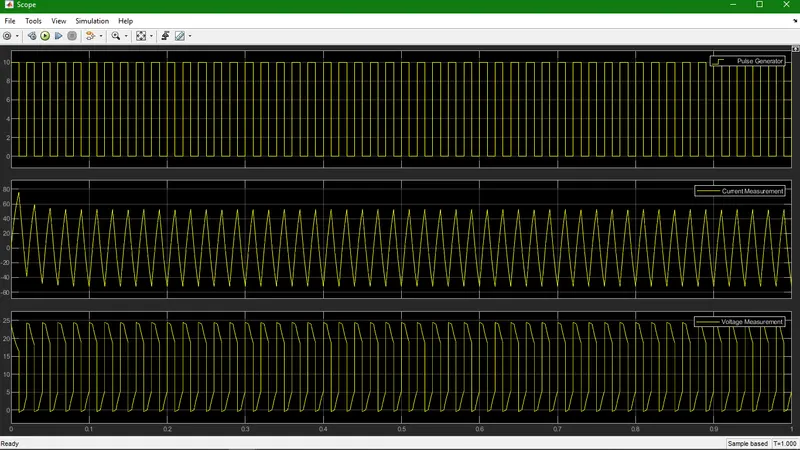
3. Explain in a brief about operation of BLDC motor.
Answer 3.
- Working Principle and Operation of BLDC Motor
- The digital signal processor (DSP)-based controller, and the power electronics based power converter, Position sensors H1, H2, and H3 sense the position of the machine rotor. The rotor position information is fed to the DSP-based controller, which in turn supplies gating signals to the power converter by turning on and off the proper stator pole windings of the machine.The torque and speed of the machines are controlled.
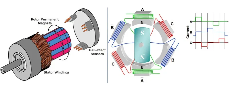
- Brushless DC motors exhibit reduced energy use, long life, low noise, compact size and light weight characteristics.
- Brushless DC motors are common in industrial applications across the world. At the most basic level, there are brushed and brushless motors and there are DC and AC motors. Brushless DC motors, as you may imagine, do not contain brushes and use a DC current.
- A brushless DC electric motor (BLDC motor or BL motor), also known as an electronically commutated motor (ECM or EC motor) or synchronous DC motor, is a synchronous motor using a DC electric power supply. It uses an electronic closed loop controller to switch DC currents to the motor windings producing magnetic fields which effectively rotate in space and which the permanent magnet rotor follows. The controller adjusts the phase and amplitude of the DC current pulses to control the speed and torque of the motor. This control system is an alternative to the mechanical commutator(brushes) used in many conventional electric motors.
- Working of BLDC motor
-
The brushless DC motors is driven by an electronic drive which switches the supply voltage between the stator windings as the rotor turns. The rotor position is monitored by the transducer. which supplies information to the electronic controller and based on this position, the stator winding to be energized is determined.This electronic drive consists of transistors (2 for each phase) which are operated via a microprocessor.
-
The magnetic field generated by the permanent magnets interacts with the field induced by the current in the stator windings, creating a mechanical torque. The electronic switching circuit or the drive switches the supply current to the stator so as to maintain a constant angle 0 to 90 degrees between the interacting fields. Hall Sensors are mostly mounted on the stator or on the rotor. When the rotor passes through the hall sensor, based on the North or South Pole, it generates a high or low signal. Based on the combination of these signals, the winding to be energized is defined. In order to keep the motor running, the magnetic field produced by the windings should shift position, as the rotor moves to catch up with the stator field.
-
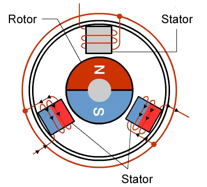
In a 4 pole, 2 phase brushless dc motor, a single hall sensor is used, which is embedded on the stator. As the rotor rotates, the hall sensor senses the position and develops a high or low signal, depending on the pole of the magnet (North or South). The hall sensor is connected via a resistor to the transistors. When a high voltage signal occurs at the output of the sensor, the transistor connected to coil A starts conducting, providing the path for the current to flow and thus energizing coil A. The capacitor starts charging to the full supply voltage. When the hall sensor detects a change in polarity of the rotor, it develops a low voltage signal at its output and since the transistor 1 doesn’t get any supply, it is in cutoff condition. The voltage developed around the capacitor is Vcc, which is the supply voltage to the 2nd transistor and coil B is now energized, as current passes through it.
- BLDC motors have fixed permanent magnets, which rotate and a fixed armature, eliminating the problems of connecting current to the moving armature. And possibly more poles on the rotor than the stator or reluctance motors. The latter may be without permanent magnets, just poles that are induced on the rotor then pulled into arrangement by timed stator windings. An electronic controller replaces the brush/commutator assembly of the brushed DC motor, which continually switches the phase to the windings to keep the motor turning. The controller performs comparative timed power distribution by using a solid-state circuit instead of the brush/commutator system.
-
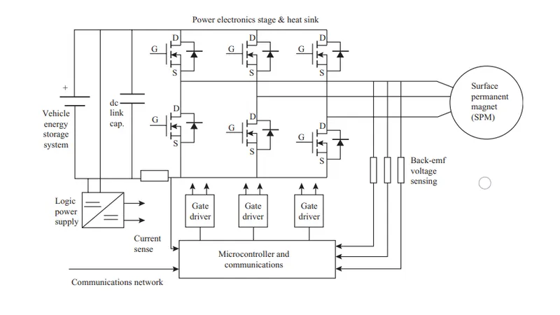
- The major components of a brushless dc motor drive
- Power electronic inverter stage and thermal management cold plate
- Gate driver assemblies for controlling the power switches
- Communications,current sensing and controller
- Logic power supply for powering the controller,gate drivers and sensors
- The dc link capacitor necessary to circulate ripple currents from the motor
- The surface permanent magnet motor
- The major advantages of a BLDC motor
- High efficiency
- Compactness
- Ease of control
- Ease of cooling
- Less noise emissions due to absence of brushes
- Low maintenance, great longevity, and reliability
- The major disadvantages of a BLDC motor
- Safety
- High-speed capability
- Magnet demagnetization
- Limited constant power range
- Inverter failures in BLDC motor drives
- High motor cost due to earth magnet
- Applications of Brushless DC motor
- Automotive application (Electric vehicles, hybrid vehicles, and electric bicycles)
- Washing machines, compressors and dryers
- Fans, pumps and blowers
- Industrial application
- Computer components
- Consumer electronicsAutomotive
- Heating and ventilation
- Industrial engineering
- Model engineering
- Types of BLDC motor in term of Rotor
- The rotor, made of a magnet, is rotated by magnetic fields that are generated by the current flowing through the stator windings. The current is switched by the sensor and electronic circuit.
- Inner rotor type (the rotor is inside the stator)
- Outer rotor type (the rotor is outside the stator)
- Inner rotor type
- Advantages of Inner rotor type
- Easy to get large torque.
- Speed is stable at constant rotation.
- Disadvantages of Inner rotor type
- The rotor is large so that's why motion is slow.
- The outside rotor requires appropriate safety measures.
- Outer rotor type
- Advantages of Outer rotor type
- The rotor is small so that's it can run rast.
- The coil is located on the outside and the level of heat dissipation is high.
- Disadvantages of Outer rotor type
- Difficult to obtain high torque.
- Magnets loss magnatic power due to centrifugal force.
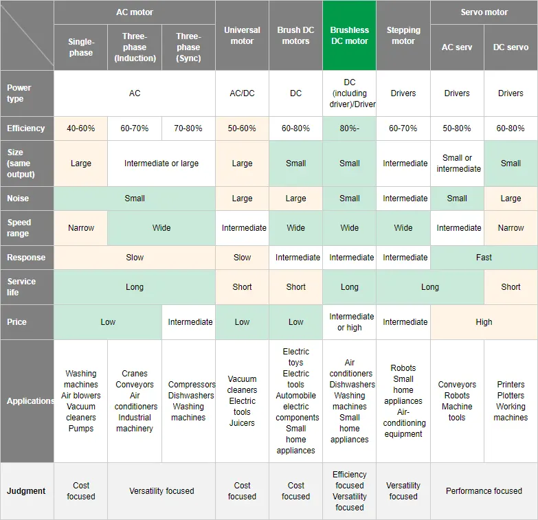
- BLDC motor compare to other motor