Week-7 Challenge: DC Motor Control
AIM : A. Explain a MATLAB demo model named ‘Speed control of a DC motor using BJT H-bridge’.
B. Comment on the armature current shoot-up from the scope results.
C. Refer to the help section of ‘The Four-Quadrant Chopper DC Drive (DC7) block’. Compare it with the H-bridge model.
2. Develop a 2-quadrant chopper using simulink & explain the working of the same with the relevant results. (Refer to article - Multiquadrant operation of motor )
3. Explain in a brief about operation of BLDC motor.
ANS 1 :
In the MATLAB/SIMULINK documentation we can search for the simulation model 'Speed control of a DC motor using BJT H-bridge'. It is used to generate a chopped voltage and to control the sped of the DC motor. This model can be opened in SIMULINK documentation itself. As the name suggests it uses a BJT (Bipolar junction transistor) which is a type of a transistor that uses both electrons and holes as charge carriers hence the name bipolar. Other transistors such as FETs (Field effective transistor) are unipolar transistors meaning that they only use one type of charge carrier. Bjts are used for switching and amplifying applications. BJTs have a 3 terminal which are Emitter (E), the base (B) and the collector (C). Current flows in only the emitter and the collector and the amount of current that flows through them is controlled by the base. BJTs are semiconductors in their working and so there 2 types of BJTs : NPN and PNP type.
- PNP Transistor :
This type uses 2 p-type semi conductors and one n- type semiconductor. The n-type semiconductor will be base of the transistor. The emitter terminal is more positive in relation to the collector and base terminals. The base terminal supplied with voltage and it operates the transistor by switching between ON and OFF states. When the base voltage decreases with respect to the emitter voltage the transistor is in the ON state.
- NPN Transistor :
This type uses 2n-type semi conductors and one p-type semi conductors. The p-type semiconductor will be the base of the transistor. Construction wise it is exactly the same as the PNP type having 3 terminals. The terminal is connected to the negative voltage supply . The base terminal is supplied with a voltage and controls the transistor being either in an ON or OFF state. when the base voltage increases with respect to the emitter voltage the transistor will be in the ON state.
- BJT H-Bridge :
When the BJT is conducting i.e. operating in the saturated region thee will be a forward voltage developed between the collector and the emitter . An 1GBT is used to model the BJT because of this the switch is controlled by a SIMULINK signal. the DC motor used in this model is preset to with specifications 5HP,24v,1750rpm. it simulates a fan type load where the load is proportional to the square of the speed. The mean armature voltage can be varied between 0 and 240V when the duty cycle is changed anywhere from 0 to 100%. The duty cycle can be changed from the pulse generator block.
The H-bridge consists of 4BJT and diode pairs. Two transistors are switched on simultaneously : Q1 and Q4 or Q2 and Q3. when Q1 and Q4 are fired a positive voltage is applied to the motor and the diodes D2 and D3 operate as free wheeling diodes when Q1 and Q4 are switched off. similarly when Q2 and Q3 are fired a negative voltage is applied to the motor and the diodes D1 and D4 operate as free wheeling diodes when Q2 and Q3 are switched off. By default the motor will start in the positve direction and has a preset duty cycle of 75% with a mean DC voltage of 180V. At t = 0.5 sec the armature coltage will reverse and the motor will run in negative direction.
This is the SIMULINK mode for BJT H-bridge used in the speed control of a DC motor.
Second part of the model :
here we can see the 'Pulse generator 500Hz' block. If we open we can see the settings
As we can see the pulse generatoris already preset with some settings. The pulse width field allows us to modify the duty cycle of the motor and hence we can prevent the motor current from shooting up when the motor changes its direction from forward to reverse. By default the duty cycle is 75% meaning that the voltage is supplied to the motor for 75% of the time for one cycle. For the remaining 25% the motor is off and recieves no voltage from the source. It is this alternation between ON and OFF states that aloow us to vary the voltage that is supplied to the motor and thereby control the speed of an electric vehicle.
The image below shows the output of the scope when the simulation is running using the preset values in the pulse generator block. There are 3 output graphs of angular speed, armature current and the load torque all against a time axis.
Now modify the simulation in order to prevent the initial shoot up of the armature current at the start of the cycle. This shoot up occurs whenever the armature voltage reverses direction which is every 0.5 seconds. In the second graph we can see that at the start of the cycle there is a sharp increase in the armature current that then decreases and comes to a more stable level where it remains until 0.5 seconds. When the next cycle begins the exact same effect occurs but in the negative as=xis because in this cycle the armature voltage is reversed. This frequency of reversing the voltage direction has been present in 'armature voltage control' block. Opening it will give us a dialogue box of its setting where the step time field controls the frequency at whch voltage is reversed.
If we change the duty cycle the pulse width can be control in this initial shoot up of the current every time the armature voltage direction is reversed. When the duty cycle is decreased upto 50% the output graph that is obtained is shown below :
This time the time reduced the duty cycle upto 40%. the output graph s shown as below
Here we can see that at start of the cycle in the positive armature voltage direction the armaturer current does not shoot up like it did before. The armature current increases immediately to approx 7A and it maintains that level until the next cycle where the armature voltage is reversed to -7A.
ANS 2 :
The four quadrant chopper DC drive block in MATLAB/SIMULINK represents a four quadrant DC supplied chopper drive for DC motors. it is also referred to as the DC7 motor drive in SIMSCAPE. It features closed loop speed control with four Quadrant operation. The closed loop speed control will output the armature current of the machine. using a PI current controller the chopper duty cycle corresponding to the commanded armature current is derived. The duty cycle is then compared with a sawtooth carrier signal to obtain the required PWM signals for the chopper. Compared to other DC drives the main advantage of using this four quadrant DC drive is that it van operate in all 4 quadrants. Each quadrant in its characteristics represents different mode of operation. The first quadrant is forward motoring the second quadrant is reverse braking, the third quadrant is reverse motoring and the forth quadrant is forward breaking. Another advantage is that it uses high switching frequency DC-DC converters resulting in a lower armature current ripple occurs than compared to thyristor based DC drives
the above picture is DC7 block
Detailed circuit diagram is shown below :
The four quadrant chopper Dc drive uses these 4 main blocks from the fundamental drive blocks library.
- speed controller
- current controller
- regulation switch
- chopper
4 quadrant chopper DC drives are used mainly due to their ability to work in 4 different quadrants of operation. It allows the controller to command the DC motor to rotate in the clockwise and counter clockwise directions and to perform braking. Traditional DC motors would rely on the innate friction and air resistance forces or actual physical brakes to bring the motor to rest. The other simpler option is to off the switch of the motor till it comes to rest.
OPERATION.
- Forward Motoring : Motor rotates clockwise and controller applies a clockwise drive.
- Reverse Motoring : Motor rotates anti-clockwise and controller applies an anti-clockwise drive.
- Forward Braking : Motor rotates clockwise and controller applies anti-clockwise drive
- Reverse Braking : Motor rotates anti-clockwise and controller applies a clockwise drive.
ADVANTAGES :
4 quadrant choppers have more control over the declaration of the motor and can more accurately brake the motor. This will make the deceleration more smoother. The second benefit is that it reduces the risk of current spikes which can occur when the motor is made to brake whle running at a high speed . So the controller life is generally longer with 4 quadrant choppers. A Third advantage is that 4 quadrant is that 4 quadrant choppers are more efficient because lesser energy is wasted as heat and lesser current spikes occur which means lesser power dissipation. Finally the 4 quadrant chopper makes regenerative braking possible so that when the motor is made to brake the kinetic energy which can then be used to charge a battery.
Comparison to H-Bridge :
Both BJT H-Bridge and 4 quadrant choppers have their advantages and disadvantages. H-bridges like the 4 quadrant choppers are also capable of the braking operation without using air resistance or friction or physical brakes to bring the motor to rest. 4 quadrant DC choppers are more commonly used in automobiles whereas BJT H-bridges are not capable of performing regenreative braking but they can perform dynamic braking. It is this difference that makes 4 quadrant DC choppers useful in hybrid and electric vechicles.
In 4 quadrant DC choppers the current signals are interrupted with one another to change the direction of rotation of the motor. This is done by speed reference or a drive cycle from which the speed values are converted to current signals which interrupt one another to cahnge the rotation of direction of the motor. However in BJT H-bridges the polarity of the current is reveresed to change the direction of rotation of the motor. Also the current signals in 4 quadrants DC choppers are chopped meaning that they are not continuous they are discrete and so take less time fr simulations. But in BJT H-bridges the current values are not chopped meaning that they are continuous and so take more time for simulations. Finally in 4 quadrant DC choppers a PI controller is used to control the speed and the current and in the H-bridge this is not implemented.
ANS 3 :
Blocks used for the above simulation :
- Math Function block
- Gain block
- constant block
- Add block
- DC voltage block
- Current measurement block
- Scope block
- Drive cycle block
The stop time of simulation is set to 10 seconds because the drive cycle is also 10 seconds in duration. After this the simulation is run and the output of the simulation is seen from the scope block connected to selector block
Two quadrant diagram using simulink :
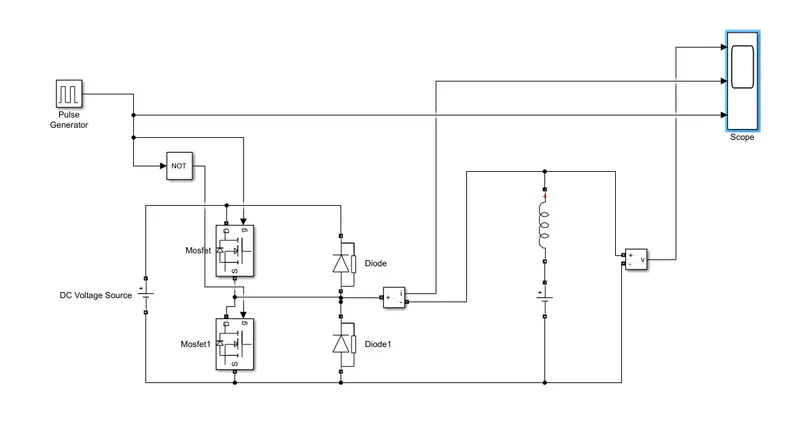
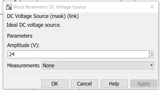
let DC voltage source be 24V.
let's consider an series RLC branch block and select the inductor L. thus block works as a load.
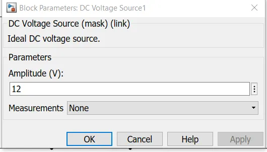
to consider LE load and DC voltage source of 12V is also connected in series with inductor.
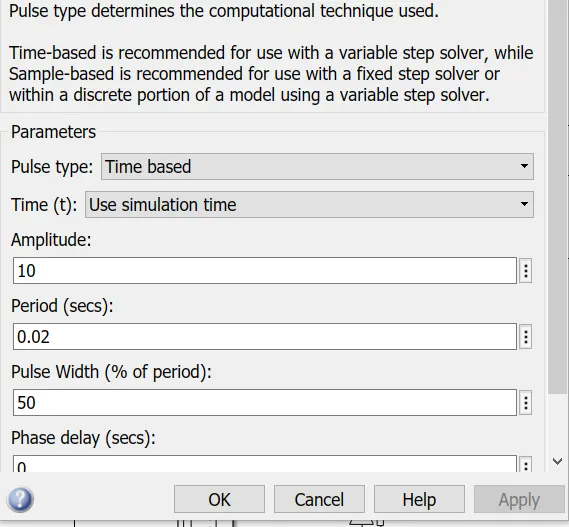
The amplitude of pulse generator is kept 10 so that we can clearly see the pulses art scope and let period be 0.02 seconds and let pulse width be 50%
RESULT :
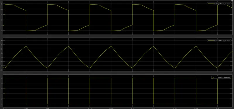
the voltage waveform is not going less than zero he minimum value of voltage is zero and maximum value is always in the positive direction. however in current waveform the current increases and decreases may be positive as well as negative. and pulse amplitude is 10 thus form pulse waveform we can see that the pulse amplitude is 10.
BLDC MOTOR : A motor converts supplied electrical energy into mechanical energy. Various types of motors are in common use. Among these, brushless DC motors (BLDC) feature high efficiency and excellent controllability, and are widely used in many applications. The BLDC motor has power-saving advantages relative to other motor types.
As their name implies, brushless DC motors do not use brushes. With brushed motors, the brushes deliver current through the commutator into the coils on the rotor. So how does a brushless motor pass current to the rotor coils? It doesn’t—because the coils are not located on the rotor. Instead, the rotor is a permanent magnet; the coils do not rotate, but are instead fixed in place on the stator. Because the coils do not move, there is no need for brushes and a commutator. (See Figure. 3.)
With the brushed motor, rotation is achieved by controlling the magnetic fields generated by the coils on the rotor, while the magnetic field generated by the stationary magnets remains fixed. To change the rotation speed, you change the voltage for the coils. With a BLDC motor, it is the permanent magnet that rotates; rotation is achieved by changing the direction of the magnetic fields generated by the surrounding stationary coils. To control the rotation, you adjust the magnitude and direction of the current into these coils.

Since the rotor is a permanent magnet, it needs no current, eliminating the need for brushes and commutator. Current to the fixed coils is controlled from the outside.
Advantages of BLDC Motors :
A BLDC motor with three coils on the stator will have six electrical wires (two to each coil) extending from these coils. In most implementations three of these wires will be connected internally, with the three remaining wires extending from the motor body (in contrast to the two wires extending from the brushed motor described earlier). Wiring in the BLDC motor case is more complicated than simply connecting the power cell’s positive and negative terminals; we will look more closely at how these motors work in the second session of this series. Below, we conclude by looking at the advantages of by BLDC motors.
One big advantage is efficiency, as these motors can control continuously at maximum rotational force (torque). Brushed motors, in contrast, reach maximum torque at only certain points in the rotation. For a brushed motor to deliver the same torque as a brushless model, it would need to use larger magnets. This is why even small BLDC motors can deliver considerable power.
The second big advantage—related to the first—is controllability. BLDC motors can be controlled, using feedback mechanisms, to delivery precisely the desired torque and rotation speed. Precision control in turn reduces energy consumption and heat generation, and—in cases where motors are battery powered—lengthens the battery life.
Applications for BLDC Motors :
They have long been used in washing machines, air conditioners, and other consumer electronics; and more recently, they are appearing in fans, where their high efficiency has contributed to a significant reduction in power consumption.
They are also being used to drive vacuum machines. In one case, a change in the control program resulted in a large jump in rotational speed—an example of the superlative controllability offered by these motors.
BLDC motors are also being used to spin hard disc drives, where their durability keeps the drives operating dependably over the long term, while their power efficiency contributes to energy reduction in an area where this is becoming increasingly important.