Week -2
AIM : Make a Simulink model of Doorbell using solenoid block and to make a simulink model o a thermistor to sense the temperature o heater and turn on or turn off the fan as per the temperature conditions.
DOORBELL USING SOLENOID :The solenoid is a electromagnet. On passing current through the conducting wires a magnetic ield is generated around it which attracts magnetic materials. This phenomenon is used in the bell. When the switch of the bell is pressed the current passes through the circuit exciting the electromagnet and pulling the plunger towards the metal portion. this produces a ringing sound.
SIMULINK MODEL :
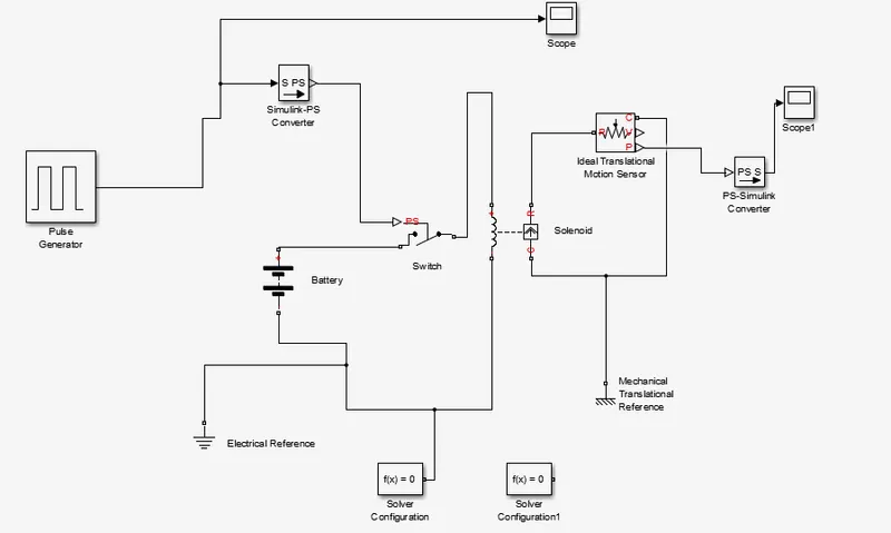
We used the pulse generator in the Above model or every two seconds it's on.
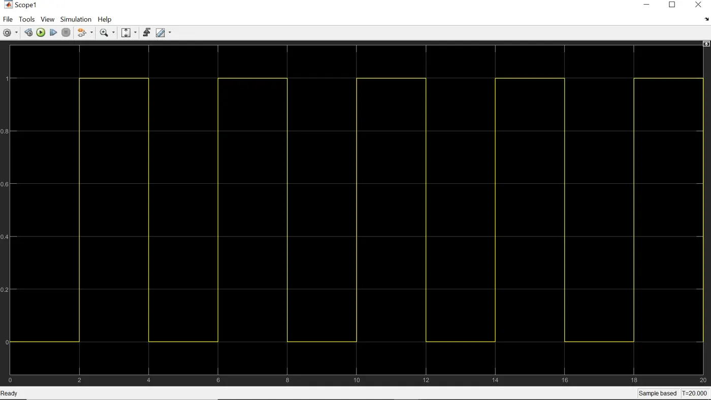
the above image shows the pulse pattern given as input. This cycle repeats or every twenty seconds.AS we want the circuit to be closed only in the interval o two seconds a switch block is used. The switch block has a threshold value of 0.8. The threshold og the pulse generator is 1. The switch will only close if the value of threshold is more than 0.8. This then connected to solenoid block which contains the plunger arrangement. Initially when the plunger is away from C the value o X is 5mm and when the plunger is near C the value o X is 0 mm. This can be seen from the output graph og the plunger distance vs. time. The position o the plunger is obtained by using Ideal translational motion sensor.
fan CONTROLLED BY THERMISTOR :
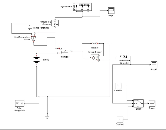
Temperature source: 20 °C from 0 to 10 seconds, 27 °C from 10 to 30 seconds, 23 °C from 30 to 50 seconds
Fan conditions: ON if the temperature above 25 °C, OFF otherwise
Blocks used in the model:
- repeating sensor
- Controlled
- signal builder
- PS-Simulink convertor
- Resistor
- Voltage sensor
- scope
- Thermistor
- battery
- Electrical reference
- Ideal temperature source
- solver configuration
- switch
- Constant
Explanation og the model
Yhe conditions o the temperature source is dehined, The sample taken as ten seconds and the whole simulation time was taken as 5seconds
Battery and the resistor is connected in the thermistor circuit. A voltage sensor was given given across the resistor to measure the voltage change during the different temperature inputs. Theresistance can be set to any value but it should not be changed once the threshold voltage is found. The threshold temperature was given as twenty five degree Celsius and the corresponding voltage over the resistor was not found, through a display connected to the voltage sensor. AT this time the signal generator was given only one value. the output from the voltage was also given inot a switch which is linked to a lamp which displays different colours based on the logical conditions.