Week-7 Challenge: DC Motor Control
1.a) Explain a MATLAB demo model named ‘Speed control of a DC motor using BJT H-bridge’.
Ans:
This example shows the simulation of an H-bridge used to generate a chopped voltage and to control the speed of a DC motor.
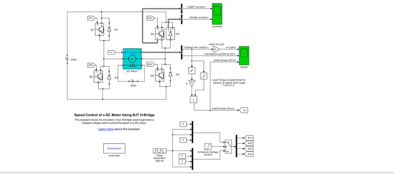
From the fig we can see that ,as there are 4 IGBT and the motor is connected between them,therefore it is called as H-bridge.
There are 4 IGBT-Q1,Q2,Q3,Q4
and 4 diode -D1,D2,D3,D4
supply volatge is 240V
There are 4 gate terminaly for each P1,P2,P3,P4
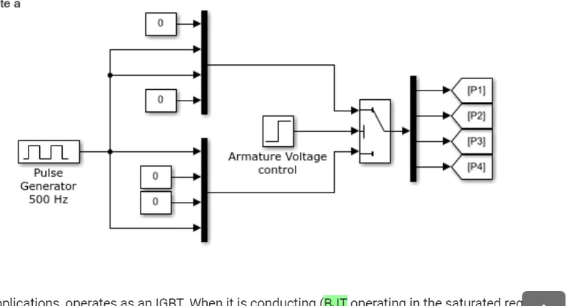
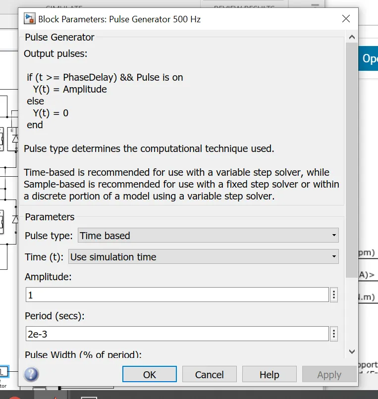
So the gate pulse is generated by using pulse generator.
The feild winding of the DC motor is exited by another 300v supply.
OPERATION:
When Q1 and Q4 are fired, a positive voltage is applied to the motor and diodes D2-D3 operate as free-wheeling diodes and when Q1 and Q4 are switched off. When Q2 and Q3 are fired, a negative voltage is applied to the motor and diodes D1-D4 operate as free-wheeling diodes when Q2 and Q3 are switched off.
B)Comment on the armature current shoot-up from the scope results.
Ans: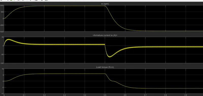
The current at motor starting can be anywhere from 5-8 times the motor's full load. Any electrical system is designed to carry and sustain a steady state during the running period. However, motor starting will cause electrical cables to carry a higher current compared to the steady-state.And after some time the armature current starts comming down to the normal level.
Armature current sudden rise and dip when the direction of the motor get changed.
C)Refer to the help section of ‘The Four-Quadrant Chopper DC Drive (DC7) block’. Compare it with the H-bridge model.
Ans: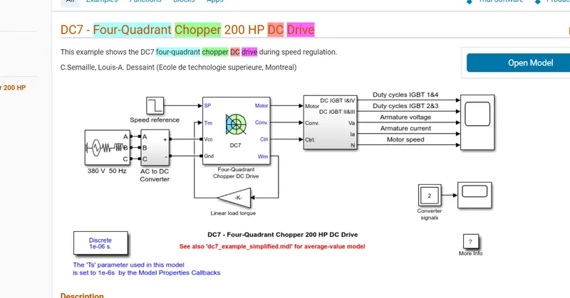 \
\
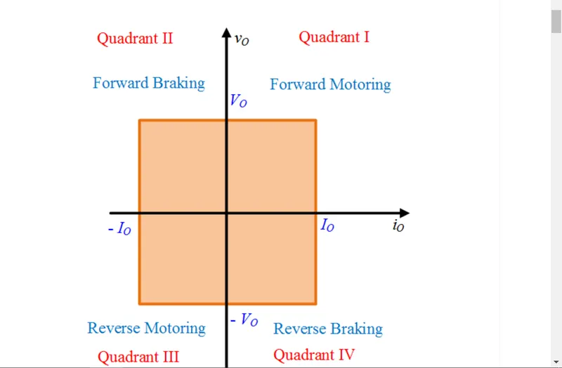
| 4 Quadrant Chopper | H bridge |
| 1). Four-Quadrant Chopper can operates in all four modes | 1)can operate only in two Modes |
| 2)Forward Motoring,Forward Braking, Reverse Motoring and Reverse Braking | 2)Forward and Reverse |
| 3) In Four-Quadrant Chopper Regenerative Braking is possible | 3)Not possible |
| 4)More advantages over H bridge and complex. | 4) Less complex design. |
| 5)More sutable for EV application. | 5) Less suitable. |
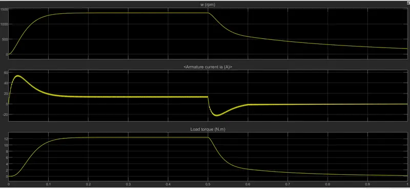
2. Develop a 2-quadrant chopper using simulink & explain the working of the same with the relevant results.
Ans: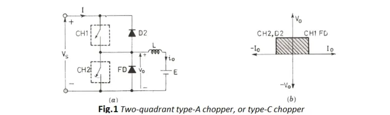
i.The two quadrant chopper is a DC-DC Control device
ii.In this type of chopper the voltage will always be in a single direction ie positive.
iii.But the current direction can be positive as well as negative.
iv.so this chopper mainly operate in 2 quadrant,1 &2.
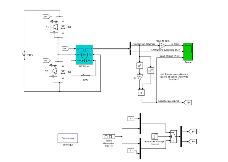
working:
i.There are 2 IGBT Q1 and Q2, and 2 diode D1 and D2.
ii.When Q1 is turned on the positive supply from the source is given to the motor and D2 diode is turned on.
iii.When Q2 is turned on the negative load current is supplied to the motor and diode d1 is turned on.
iv.This type of model is maily used when we consider regenerative breaking into consideration.
v.when Q1,D2 is on motor is in the 1st quadrant operation and it is in the forward motering region.
vi.when Q2,D1 is on motor is in the 2ns quadrant operation and now it is in the forward breaking region.(regenerative breaking)
3)Explain in a brief about operation of BLDC motor.
Ans:
i.Brushless DC (BLDC) motors deliver high efficiency, torque and speed, and are available in dimensions to suit a wide variety of applications.
ii.Depending on the various application we need different type of motors ,so how could we find the best motor with high efficiency for our application.
iii.Conventional DC motors use a stationary magnet with a rotating armature combining the commutation segments and brushes to provide automatic commutation.
but in the BLDC motor the commutation and the brushes segments are completely removed.
iv.The permanent magnet is rotating whereas the windings are part of the stator and can be energized without requiring a commutator-and-brush system.
v.The commutation of the brushless DC motor is made electronically and can be done either by looking at the back-EMF of the motor or by using a position sensor.
The position sensor is called as the hall efect sensor.
vi.Even while operating at extremely high speeds, BLDC achieve a long, trouble-free life, as there is no mechanical commutation. They have mainly linear motor characteristics, with excellent speed and position control. In brushless motors, static windings are attached to the motor housing, resulting in improved heat dissipation and overload capability. Brushless motors are high efficiency.
Operation:
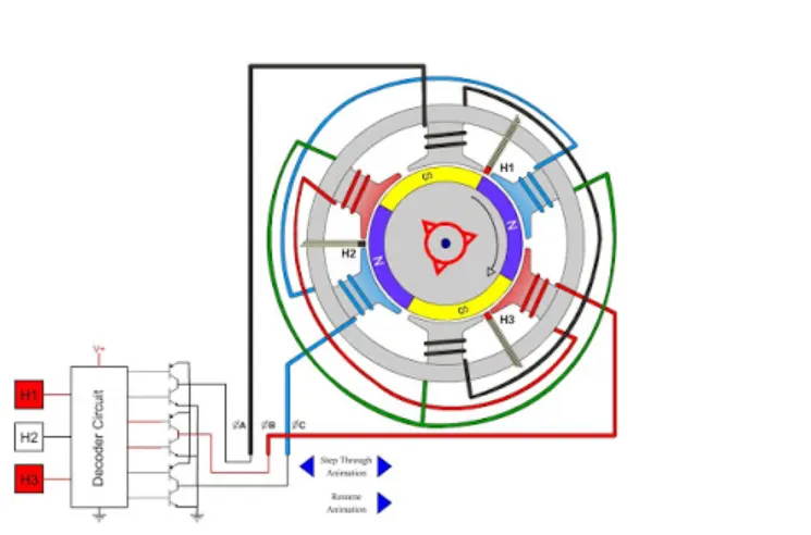
The H1 H2 H3 are the hall sensors.
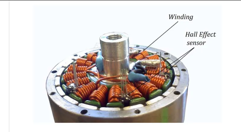
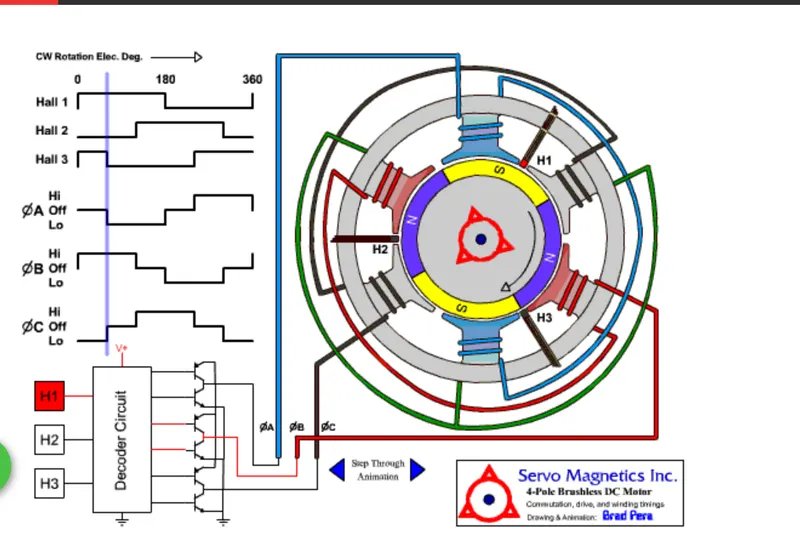
Brushless motors are not self-commutating, and hence are more complicated to control.
the above fig has 3 phase -A,B&C,when ever the S pole of the magnet moves infront of the hall sensor it gives the output and remains on till the N pole pass infront of it.The decoder circuits decodes the output from the hall sensor and accordingly activates the required pahse to roatate the motor.As now we know the position of the rotor we can control the A,B,C phase to control the motor and give a constant torque output.
i.The BLDC drive system is based on the feedback of rotor system at fixed points for commutation of the phase currents.
ii.The BLDC motor requires quasi-rectangle shaped currents fed into the machine.From the above fig we can see the hall sensor output and the Per phase rectangular inputs.
iii.Alternatively, the voltage may be applied to the motor every 120°, with current limit to hold the current within motor capabilities.
iv.Because the phase currents are excited in synchronism with the constant part of the back emf, constant torque is generated.
v.The electromagnetic torque of the BLDC motor is related to the product of phase, back emf and current. The back emf in each phase are trapezoidal in shape and are displaced by 120 electrical degree with respect to each other in 3 phase machine.
vi.A rectangle current pulse is injected into each phase so that current coincides with the ack emf waveform; hence the motor develops an almost constant toque.