Week-7 Challenge: DC Motor Control
Aim :
Understanding the DC motor control drive.
Objective :
- A. Explain a MATLAB demo model named ‘Speed control of a DC motor using BJT H-bridge’ and explain the reason behind armature current shoot-up from the scope results.
- Refer to the help section of ‘The Four-Quadrant Chopper DC Drive (DC7) block’. Compare it with the H-bridge model.
- Develop a 2-quadrant chopper using Simulink & explain the working of the same with the relevant results.
- Explain in a brief the operation of the BLDC motor.
Introduction :
What is a Power Converter?
A converter is an electrical circuit that accepts a DC input and generates a DC output of a different voltage, usually achieved by high frequency switching action employing inductive and capacitive filter elements.
A power converter is an electrical circuit that changes the electric energy from one form into the desired form optimized for the specific load. A converter may do one or more functions and give an output that differs from the input. It is used to increase or decrease the magnitude of the input voltage, invert polarity, or produce several output voltages of either the same polarity with the input, different polarity, or mixed polarities such as in the computer power supply unit.
The DC to DC converters is used in a wide range of applications including computer power supplies, board-level power conversion and regulation, dc motor control circuits, and much more.
The converter acts as the link or the transforming stage between the power source and the power supply output. There are several kings of converters based on the source input voltage and the output voltage and these fall into four categories namely the AC to DC converter known as the rectifier, the AC to AC cyclo converter or frequency changer, the DC to DC voltage or current converter, and the DC to AC inverter.
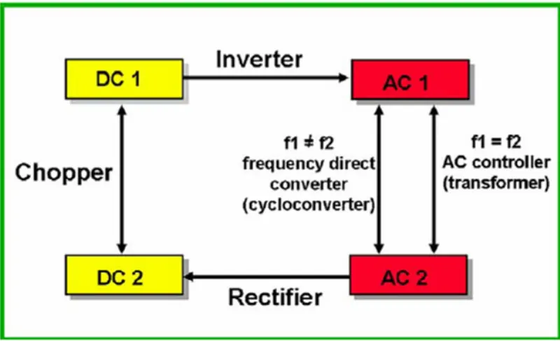
Fig 1 Power converter specifications
The converter uses nonlinear components such as the semiconductor switches, and linear reactive components such as the inductors, transformers and capacitors for intermediate energy storage as well as current and voltage filtering. The size, weight, and cost of the converter are largely determined by these components.
There three basic converter circuits that are widely used in DC to DC converters are the buck, boost, and the buck and boost. These configurations are the most used topologies due to their simplicity and use of fewer components. Each has its advantages and drawbacks which determines the suitability for any specific application.
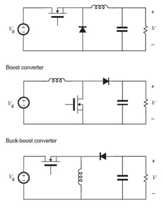
Figure 2 non-isolated converter circuit arrangements
The buck converter is a step-down, the boost a step-up while the buck-boost is both step-up and step-down. All these are non-isolated and use the inductor as the energy transfer element and are mostly used in board-level power conversion and regulation.
The isolated dc to dc converters use a transformer to provide the isolation, multiple outputs, a different voltage level, or polarity depending on the turns ratios and directions of the windings.
They are based on the non-isolated topologies but with the inclusion of a transformer. The commonly used types are, the full-bridge, the half-bridge, forward, and the push-pull converters, which are the isolated versions of the buck; and the flyback which is the isolated version of the buck-boost converter.
Converters are widely used in electronic equipment, power supplies, and other circuits requiring specific voltage and current levels other than the available raw supply energy. The converters provide any type of the required voltage at the desired magnitude. With a proper design and use of the almost ideal components, the available methods of conversion offer a variety of reliable and efficient energy to power most electronic devices and components.
Switching Technique is adopted from Power Electronics to control the Voltage and Current for Electric Motor. This avoids a high amount of losses by replacing Resistor with and Power Module/Switch. And these Power Modules are operated at high Frequency where the Rated Battery Voltage (Vbat) can be reduced to the desired voltage by ON-OFF of Modules.
Switching Frequency will be in such a way that it utilizes Vbat & switches low and High to maintain the Average desired Voltage. The principle behind the Power Modules is not controlling the Magnitude of the Voltage but the duration of High & Low values of Voltage resulting in the desired voltage level. This ON-OFF Switching Frequency is referred to in terms of Duty Ratio (d) = (ON) time/(ON+OFF) time
By changing the Duty Ratio of the Power Modules, we can vary the voltage from one level to another level. Vavg = Vbat * d
BJT:
A bipolar junction transistor (BJT) is a type of transistor that uses both electrons and electron holes as charge carriers. In
contrast, a unipolar transistor, such as a field-effect transistor, uses only one kind of charge carrier. A bipolar transistor allows a
small current injected at one of its terminals to control a much larger current flowing between two other terminals, making the
device capable of amplification or switching.
BJTs use two junctions between two semiconductor types, n-type and p-type, which are regions in a single crystal of material
The junctions can be made in several different ways, such as changing the doping of the semiconductor material as it is grown, by
depositing metal pellets to form alloy junctions, or by such methods as diffusion of n-type and p-type doping substances into
the crystal.
Solutions :
- Simulate ‘Speed control of DC motor using BJT H-bridge circuit’ and reduce the sudden shoot up of armature current.
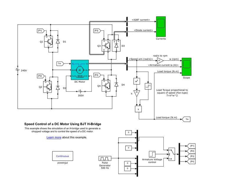
Working :
The Bipolar Junction Transistor (BJT) when used for power switching applications, operates as an IGBT. When it is conducting (BJT operating in the saturated region), a forward voltage Vf is developed between collector and emitter (in the range of 1 V). Therefore, the IGBT block can be used to model the BJT device.
The IGBT block does not simulate the gate current controlling the BJT or IGBT. The switch is controlled by a Simulink® signal (1/0). The DC motor uses the preset model (5 HP 24V 1750 rpm). It simulates a fan type load (where Load torque is proportional to the square of speed). The armature means voltage can be varied from 0 to 240 V when the duty cycle (specified in the Pulse Generator block) is varied from 0 to 100%.
The H-bridge consists of four BJT/Diode pairs (BJT simulated by IGBT models). Two transistors are switched simultaneously: Q1 and Q4 or Q2 and Q3. When Q1 and Q4 are fired, a positive voltage is applied to the motor, and diodes D2-D3 operate as free-wheeling diodes when Q1 and Q4 are switched off. When Q2 and Q3 are fired, a negative voltage is applied to the motor, and diodes D1-D4 operate as free-wheeling diodes when Q2 and Q3 are switched off.
Simulation :
Basic motor parameters :
Power = 5 HP
Rated Voltage = 240 V
Rated Speed = 1750 RPM
duty cycle of 75%- the current or supply will flow for 75% for a time period
DC voltage of 180V
At t= 0.5 sec., the armature voltage is suddenly reversed and the motor runs in the negative direction.
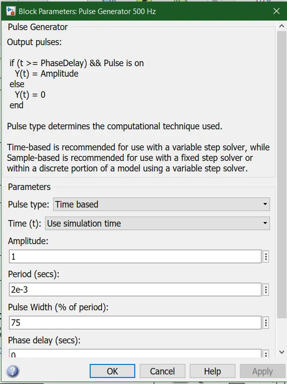
The motor starts in the positive direction with a duty cycle of 75% that is the graph of current will be positive. But at t= 0.5 sec., the armature voltage is suddenly reversed and the motor runs in the negative direction. 'Scope' shows motor speed, armature current, and load torque and 'Currents' shows currents flowing in BJT Q3 and diode D3.
Now, with the graph, it is observed that the motor has the maximum of around rpm of 950 rpm as an omega in Forwarding motoring and there is the sudden surge of 35A of current at the starting which later drops down to stable value till 0.5th sec and after that, the curve goes beyond zero which is negative indicating the Reverse motoring of -950.8rpm.
As in the Switch block, the threshold time is given as 0.5, So after 0.5th sec the current flow to the motor is changed in opposite direction thus reverse motoring happens.
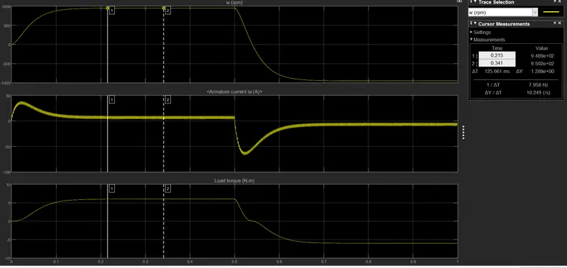
Ans-
The reason why there is sudden shooting up of current in the motor is explained in the following points:
- The DC resistance of rotor winding is minimum, thus when the power is switched ON it would draw a current equal to V/R, which would be very high and if the motor does not rotate then the winding would burn out. But when the motor starts rotating then a back EMF is built with opposes the input EMF and the resultant EMF is very small to maintain the current within the limit which would always be a function of RPM.
- Inrush current of a DC motor is given by i=(V−E)/r where r is the armature resistance, V is the terminal voltage and E is the developed back emf which is directly proportional to the speed of the motor (N). During starting the motor was initially standstill, hence the speed of the motor (N) as well as back emf (E) is zero. It means that the inrush current during start is only V/r. For a DC motor, the armature resistance is very small hence the inrush current drawn is very high. As the motor starts rotating, E develops and hence current value falls.
To reduce the shoot up of armature, we can reduce the pulse width to 45% which means the duty cycle will be kept at 45%.
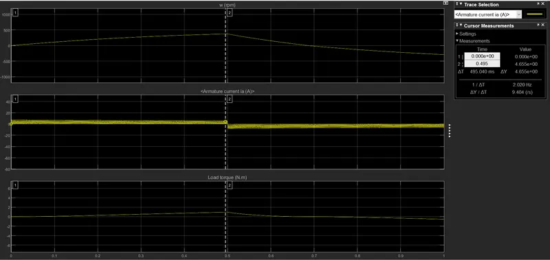
Now, the above graph shows the results obtained by changing the duty cycle to 45%.
The armature current has a significant stable current flow and hence the sudden shoot-up of current is reduced as seen in the graph is somewhat smooth.
- The current value obtained was 5.97A for the positive side and 8.23 A after changing the polarity.
- Earlier the motor speed was 950rpm which later obtained was around 375rpm.
- For the 45% duty cycle, the torque shows a drop from 6 Nm to 1 Nm because the torque is proportional to the current flowing to the armature.
- Referring article of ‘Four-Quadrant Chopper DC Drive (DC7) block’ and Compare it with the H-bridge model.
A four-quadrant chopper is a chopper that can be operated in all four quadrants. The power can flow either from source to load or load to source in this chopper. In the first quadrant, a Class-E chopper acts as a Step-down-chopper, whereas in the second quadrant it behaves as a Step-up-chopper. This type of chopper is also known as Class-E or Type-E chopper.
Four-Quadrant Chopper block represents a four-quadrant controlled chopper for converting a fixed DC input to Variable DC
Output. The block contains two bridge arms. Each bridge arm has two Switching devices.
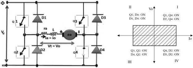
Fig: Four-Quadrant Chopper or Type E chopper
The circuit of a four-quadrant chopper or class-E chopper consists of four semiconductor switches CH1 to CH4 and four diodes D1 to D4. The four diodes are connected in anti-parallel.
Working operation:
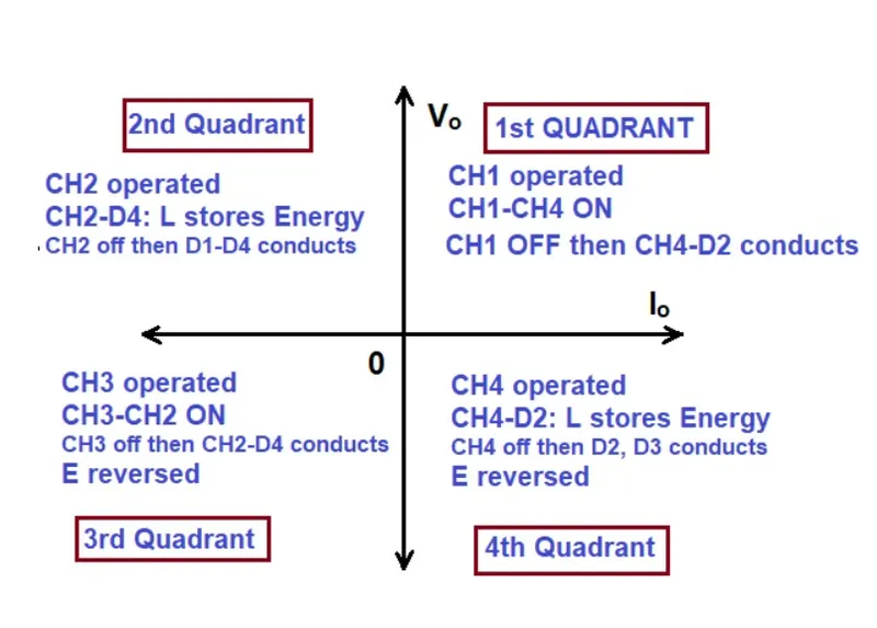
First Quadrant :
For the first quadrant operation, thyristor CH4 is kept on, thyristor CH3 is kept off and thyristor switch CH1 is operated. WithCH1, CH4 ON, the load gets directly connected to the source and armature voltage (Vo = Vs) and armature Current (Io) begins flow
Here both Vo and Io are positive giving first quadrant operation.
when CH1 is turned off, positive current freewheels through CH4, D2. In this manner, Vo, Io can be controlled in this first quadrant, and Motor rotates in the forward direction, so it is called Forward Motoring.
Second Quadrant :
Here thyristor CH2 is operated and CH1, CH3, and CH4 are kept off. With CH4 on, reverse or negative current flows through L, CH2, D4, and E. During the operation time of CH2, the armature inductance ‘L ’ stores energy during the time CH2 is on. When CH2 is turned off, the current is fed back to the source through diodes D1, D4. Note that here (E+L(di/dt)) is more than the source voltage Vo. As the Vs is positive and Io is negative, it is a second quadrant operation that gives forward braking mode. In that power is fed back from armature to source. It is called forwarding Regenerative Braking.
Third Quadrant :
For the third quadrant operation, thyristor CH1 is kept off, CH2 is kept on and CH3 is operated, polarity of armature back emf (E) must be reversed for this quadrant operation. With thyristor CH3 is on, armature gets connected to source V. so that both Vo ,Io is negative, leading to third quadrant operation.
When CH3 is turned off, negative current freewheels through CH2, D4. In this manner, only Vo and Io can be controlled in the third quadrant. The motor rotates in a reverse direction and it is called Reverse Motoring.
Fourth Quadrant :
Here thyristor CH4 is operated and other devices kept off, back emf (E) must have its polarity reversed as in third quadrant operation. With CH4 on, positive current flows through CH4,D2,L, and E (armature). Armature inductance L stores energy during the time CH4 is on.
When CH4 is turned off, the current is fed back to the source through diodes D2, D3. Here armature voltage Va is negative, but Ia is positive, leading to the chopper drive operation in the fourth quadrant. Also, power is fed back from armature to source. This is known as Reverse Regenerative Braking
Comparison of Four-Quadrant chopper DC7 block vs H-bridge model :
- Four-Quadrant Chopper can operate in all four modes (Forward Motoring, Forward Braking, Reverse Motoring and Reverse Braking), but H-bridge can operate only in two modes (Forward and Reverse).
- In Four-Quadrant Chopper Regenerative Braking is possible, but H-bridge Regenerative Braking is not possible.
- H-bridge is an electronic circuit that switches the polarity of the voltage applied to the load and a Four-quadrant Chopper is an electronic switch that is used to interrupt one signal under the control of another.
- The Four-Quadrant Chopper model gives better efficiency and high energy(power) storage than the H-bridge model.
- Develop a 2-quadrant chopper using Simulink & explain the working:
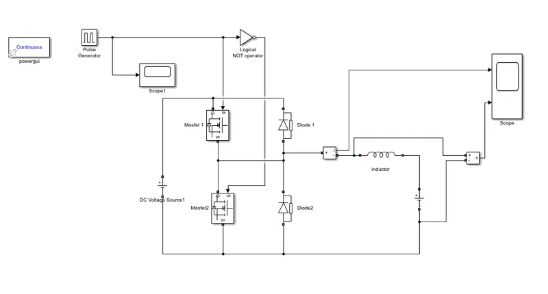
- To start with the two-quadrant chopper drive, we have first given the input from the DC source voltage. The voltage value is kept to be 32V.
- For Power switches or transistors, we will be using the MOSFET(metal-oxide-semiconductor- field-effect transistor)coupled with the Diode in parallel. There will be two pairs of these switches and diode so that we can operate the model in 2- quadrants and all these are connected accordingly.
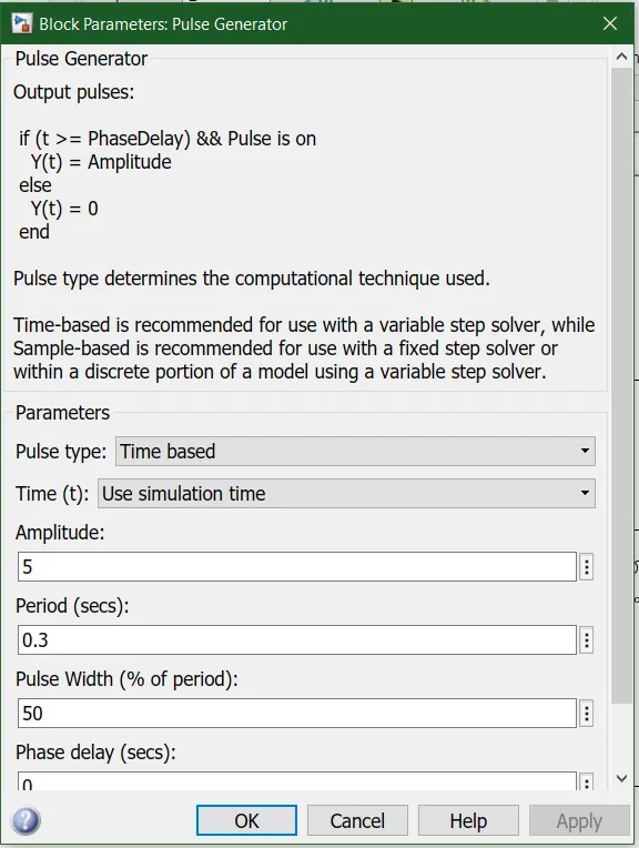
- Now, the pulse generator with 50% duty cycle, 0.3 sec, and 5 as an amplitude. The output of the generator is connected to the NOT operator which ensures that only one switch is working at a time. Then it is further connected to the gate of the switches.
- The inductor is provided which will store the current when switch 1 is turned off. Then for the load, we have used another dc source with a voltage of 16V as shown in the below diagram.
- To measure the current and voltage, the measuring block is used whose output can be visualized using the scope.
- We need the powergui block to simulate any Simulink model containing Simscape Electrical Specialized Power Systems blocks. It stores the equivalent Simulink circuit that represents the state-space equations of the model.
Working :
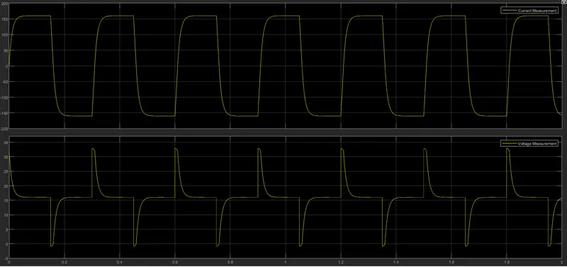
- In a Two-quadrant Chopper, the average voltage will be always positive but the average load current might be positive or negative. The two Switches CH1 and CH2 should not be turned on simultaneously as the combined action may cause a short circuit in supply lines.
- When the chopper CH1(MOSFET1) is ON, the current flows from the source to load the inductor stores energy. The current flow from MOSFET 1 to the inductor to the load means the voltage and current are flowing from the source to load.
- When Ch1 turns OFF, the freewheeling diode starts conducting and the output voltage will be equal to V . The direction of the load current will be reversed since the inductor is now discharging itself and the current will be flowing towards the source.
- For the regenerative braking, the load current will be negative when the CH2 is on. The current complete its path from the mosfet2 to the negative terminal of load diode to the diode 2.
4. Brief about the BLDC motor :
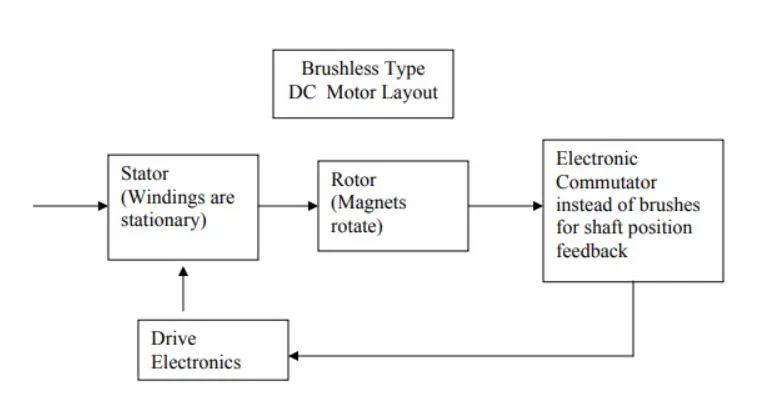
It often helps to explain how a brushed DC motor works first, as they were used for some time before brushless DC motors were available. A brushed DC motor has permanent magnets on the outside of its structure, with a spinning armature on the inside. The permanent magnets, which are stationary on the outside, are called the stator. The armature, which rotates and contains an electromagnet, is called the rotor.
In a brushed DC motor, the rotor spins 180-degrees when an electric current is run to the armature. To go any further, the poles of the electromagnet must flip. The brushes, as the rotor spins, make contact with the stator, flipping the magnetic field and allowing the rotor to spin a full 360-degrees.
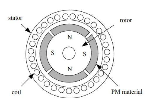
A brushless DC motor is essentially flipped inside out, eliminating the need for brushes to flip the electromagnetic field. In brushless DC motors, the permanent magnets are on the rotor, and the electromagnets are on the stator. A computer then charges the electromagnets in the stator to rotate the rotor a full 360-degrees.
Construction of BLDC Motor
The main design difference between brushed and brushless motors is the replacement of a mechanical commutator with an electric switch circuit. Keeping that in mind, a BLDC motor is a type of synchronous motor in the sense that the magnetic field generated by the stator and the rotor revolve at the same frequency.
Brushless Motors are available in three configurations: single-phase, two-phase, and three-phase. Out of these, the three-phase BLDC is the most common one.
The following image shows the cross-section of a BLDC Motor.
Stator
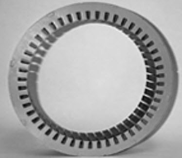
The structure of the stator of a BLDC motor is similar to that of an induction motor. It is made up of stacked steel laminations with axially cut slots for winding. The winding in BLDC are slightly different than that of the traditional induction motor.
Generally, most BLDC motors consist of three stator windings that are connected in star or ‘Y’ fashion (without a neutral point). Additionally, based on the coil interconnections, the stator windings are further divided into Trapezoidal and Sinusoidal Motors.
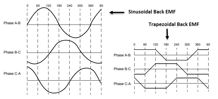
In a trapezoidal motor, both the drive current and the back EMF are in the shape of a trapezoid (sinusoidal shape in case of sinusoidal motors). Usually, 48 V (or less) rated motors are used in automotive and robotics (hybrid cars and robotic arms).
Rotor
The rotor part of the BLDC Motor is made up of permanent magnets (usually, rare earth alloy magnets like Neodymium (Nd), Samarium Cobalt (SmCo) and alloy of Neodymium, Ferrite and Boron (NdFeB)).
Based on the application, the number of poles can vary between two and eight with North (N) and South (S) poles placed alternately. The following image shows three different arrangements of the poles. In the first case, the magnets are placed on the outer periphery of the rotor.
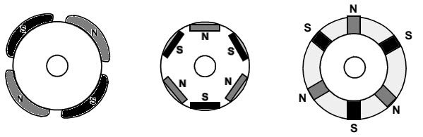
The second configuration is called a magnetic-embedded rotor, where rectangular permanent magnets are embedded into the core of the rotor. In the third case, the magnets are inserted into the iron core of the rotor.
Working Principle
Consider the following setup of three windings in the stator designated A, B and C. For the sake of understanding, let us replace the rotor with a single magnet.
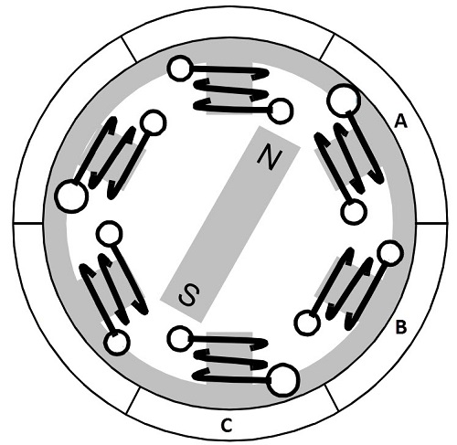
We know that when a current is applied through a coil, a magnetic field is generated and the orientation of the field lines i.e. the poles of the generated magnet will depend on the direction of the current flowing through the coil.
Using this principle, if we supply current to the coil A so that it will generate a magnetic field and attract the rotor magnet. The position of the rotor magnet will shift slightly clockwise and will align with A.
If we now pass current through coils B and C one after the other (in that order), the rotor magnet will rotate in clock wise direction.
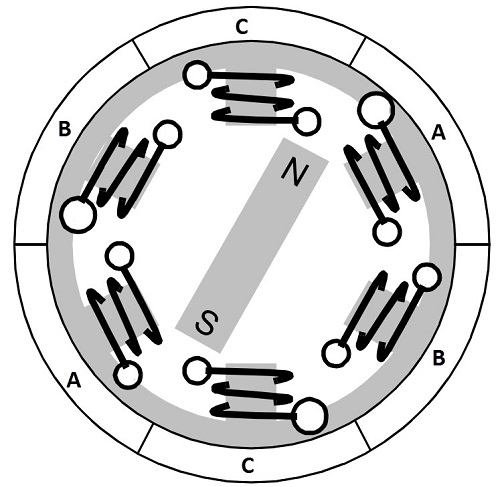
To increase efficiency, we can wind the opposite coils using a single coil so that we get double attraction. Further increasing the efficiency, we can energize two coils at the same time so that one coil will attract the magnet and the other coil will repel it. During this time, the third will be idle.
For a complete 3600 rotation of the rotor magnet, six possible combinations of the coils A, B and C are applicable and are shown in the following timing diagram.
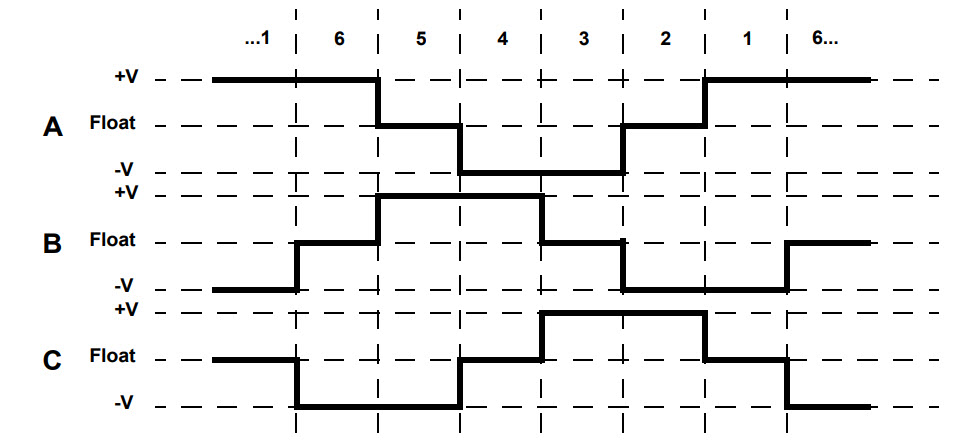
Base on the above diagram, we can confirm that at any time, one phase is positive, one phase is negative and the third phase is idle (or floating). So, based on the inputs from the Hall Sensors, we have two switch the phases as per the above diagram.
References :
https://skill-lync.com/student-projects/multi-quadrant-operation-of-dc-motor-in-simulink
https://electricalbaba.com/four-quadrant-chopper-or-class-e-chopper/
https://www.electronicshub.org/brushless-dc-motor-bldc-motor/