Week-7 Challenge: DC Motor Control
OBJECTIVE : SPEED CONTROL OF DC MOTOR USING BJT H-BRIDGE & STUYDY ARMATURE CURRENT SHOOT UP
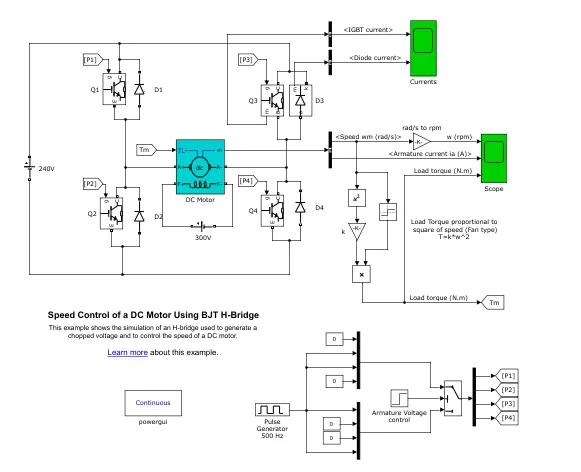
A-SOLUTION : The BJT when used for power switching applications, operates as an IGBT. When it is conducting ( BJT operating in the saturated region), a forward voltage Vf is a developed between collector and emitter (in the range of1V). Therefore, the IGBT block can be used to model the BJT device.
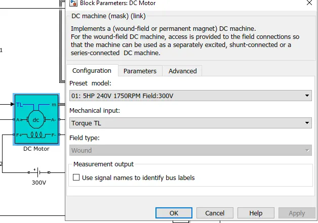
The IGBT block does not simulate the gate current controlling the BJT or IGBT. The switch is cintrolled by a Simulink SIgnal (1/0). The DC motor uses the preset model (5HP 24V 1750rpm). It simulates a fan type load(where torque is proportional to the square of speed). The armature means voltage can be varied from 0 to 240 V when duty cycle(specified in the Pulse Generator block) is varied from 0 to 100%.
The H-bridge consists of four BJT diode pairs(BJT simulated by IGBT models). Two transistors are switched simultaneously i.e Q1 & Q4 or Q2 & Q3.
When Q1 & Q4 are fired, a postive voltage is applied to motor and diodes D2-D3 operate as free-wheeling diodes when Q1 & Q4 are switched off.
When Q2 & Q3 are fire, a negative voltage is applied to the motor and diodes D1-D4 operate as free-wheeling diodes when Q2 & Q3 are switched off.
Schemetic arrangement for DC motor with BJT H bridge is shown below :-
And the parameters of DC motor is kept as :-
Armature current shoot up from the scope :-
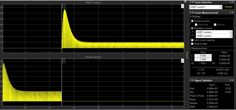
- Here the scope shows the Diode current and the IGBT current.
- In this we can see that as the Diode current is shut off (off) at 0.5s time period and IGBT current gets acted after 0.5s.
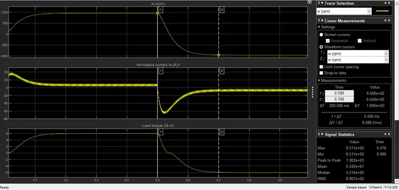
- The speed (rpm) and the armature current are linked with DC motor, Load torque is proportional to the square of speed.
- Initially we can observe that there is sudden shoot in the armature current and the speed & torque is also in positive direction.
- After time period of 0.5s sudden shoot up is acted armature current goes in negative direction and the speed decreses and torque acts in reverse direction.
B-CONTROLLING THE SHOOT UP OF CURRENT :-
- One simple way of controlling shoot up of current is to regulate the amount of voltage applied to the terminal that can be achieved using the PWM (Pulse Width Modulation).
- For experimantal calculation Pulse Width (Duty Cycle) is reduced to 45%
- As a result value of P1, P2, P3, P4 is changed that will result in the regulation of shooting of current.
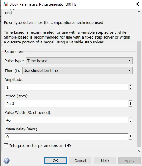
- Here when Q1 & Q4 is on and Q2 & Q3 are off, motor is generated in forward direction and in reverse direction in vice vers condition.
- Now observing the changes in parameters with the help of scope :-
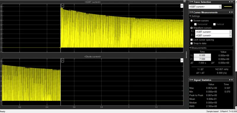
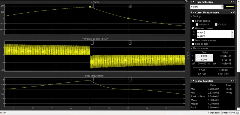
- Here we can see that after reducing the duty cycle to 45% we can observe the reduction in the shooting up of armature current which in resuts tends to control the sudden shoot in the speed of vehicle.
C- THE FOUR QUADRANT CHOPPER DC DRIVE & H BRIDGE MODEL
SOLUTION : A 200 hp DC motor is seperately excited with a constant 150v DC field voltage source. The armature voltage is provided by an IGBT converter controlled by 2 PI regulators. The converter is fed by 515V DC bus obtained by rectification of a 380V AC 50HZ voltage source. In order to limit the DC bus voltage during dynamic braking mode, abraking chopper has been added between the diode rectifier and the DC block.
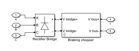
Here we can see Braking chopper added between rectifier and DC block to limit DC bus voltage.
The first regulator is a speed regulator, followed by a current regulator. The speed regulator outputs the armature current reference used by the current controller in order to obtain the electromagnetic torque needed to reach the desired speed. The speed reference change rate follows acceleration and deaceleration ramps in order to avoid sudden reference changes that could cause armature over-current and destabilize the system. The current regulator controls the armature current by computing appropriate duty ratios of 5kHz pulses of the four IGBT devices (PWM). For proper system behaviour the instantaneous pulse values ofIGBT devices 1 & 4 are opposite to those of IGBT devices 2 & 3. This generates the average armature voltage needed to obtain the desired armature current. in oreder to limit the amplitude of the current oscillations, a smoothing inductance is placed in series with the armature circuit.
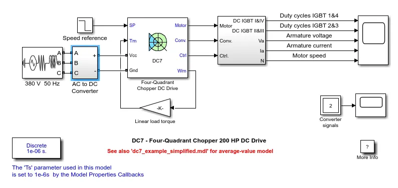
SIMULATION
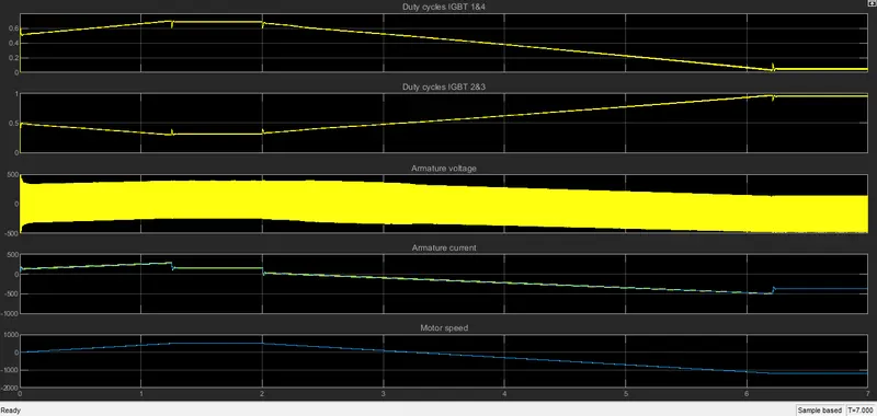
- Here we can observe the motor armature voltage and current the 4 IGBT pulses and motor speed on the scope
- The speed reference is set at 500rpm at t=0s. Moto speed follows the ramp and reaches steady state at around 1.2s
- The armature current follows current reference very well with fast response time and small ripples. here current repple freq is 5khz.
- At t=2s the speed reference reduces, the current reference decreases to reduce the electromagnetic torque and cause the motor to deaccelerate with the help of load torque.
- At t=2.2s the current reverses in order to prodece braking electromagnetic torque(dynamic braking mode) This causes the DC bus voltage to increase.
- At t=3.25s motor reaches 0 rpm and load torque reverse and become negative. The negative current now produces an accelerating electromagnetic torque to allow motor to follow negative speed ramp and later it stabilizes around its reference.
FOUR QUADRANT CHOPPER
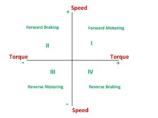
- It converts electrical energy into mechenical energy and supports motion, In braking it works as a generator converting mechenical energy to electrical energy and oppose motion.
- Motor can be providing motoring and braking opearation in both reverse and forward direction
- Power developed by motor is given by product of speed and torque.
- In 1st quad power developed is positive and is called forward motoring
- In 2nd quad power developed is negative and hence be considered as braking mode.
- Similarly 3rd quadrant is reverse motoring mode and $the quad is reverse braking mode
COMPARISON OF 4 QUADRANT CHOPPER DC7 BLOCK AND H BRIDGE MODEL :-
- 4 Quadrant chopper can operate in 4 modes ( Forward Motoring, forward braking, reverse braking, reverse motoring) wheras H bridege can operate in two modes forward and reversing.
- In 4 quadrant chopper regenerative braking is possible but in case of H bridge there is no regenerative braking.
- In 4 quadrant 2 PI regulators (Speed Regulator & Current regulator) is used to obtain electromagnetic torque used to achieve desired speed and control armature current and stablizes system but in H bridge model PI regulator is not used.
- H-bridge is often used in robotics to and other application to allow the dc motor to run in forward and reverse direction. 4 quadrant is used in various switching application used to power control and signal application.
- 4 Quadrant gives better efficiency and high power then H bridge.
OBJECTIVE-2 : 2 QUADRANT CHOPPER
SOLUTION : In this type of chopper average voltage will always be positive but the average load current might be positive or negative. The two switches CH1 & CH2 should not be turned on simultaneously as the combined action may result in short circuit. For regenerative motoring and braking these type of chopper configuration is used.
We will always get a positive voltage Vo as the frewheeling diode FD is present across the load. When the chopper CH1 is on the current flows from source to load. The inductor stores energy. When CH1 is turned off the frewheeling diode starts conducting and the output voltage Vo will be equal to Vs. The direction of the load current Io will be reversed. The current Io will be flowing towards the source. The load current will be negative when the CH2 is on. The current completes the path through diode D2.
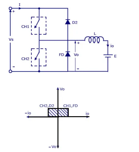
SIMULATION :-
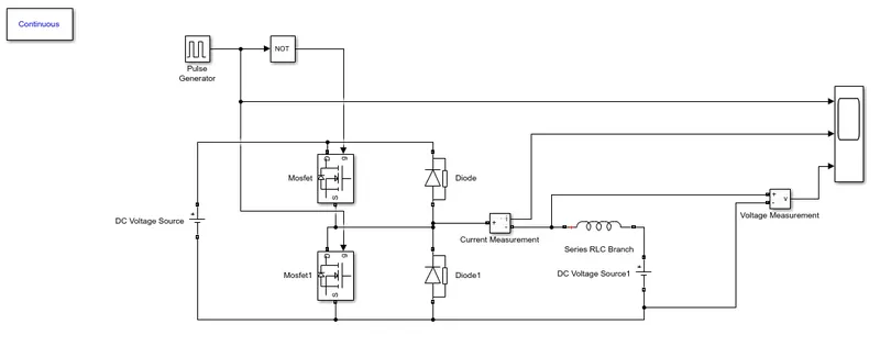
Above is the schemetic arrangement for 2 quadrant chopper
Parameterization of 2 DC voltage source is done as :-
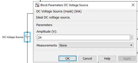
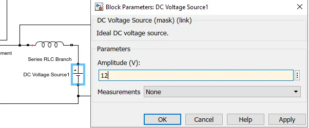
The dc voltage source is set to 24v & 12v respectively.
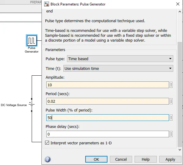
The pulse generator block is used to create gate pulse at amplitude of 50%. And not block is used to avoid the shorting of circuit.
Analyzing the results :-
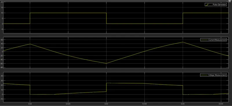
- Here we can observe the amplitude of pulse generator wave is set to 10.
- Current measurement is going from positve to negative then to positive wheras voltage waveform will not go negative its minimum value may went to zero but maximum value is in positive direction.
OBJECTIVE-3 - BLDC MOTOR
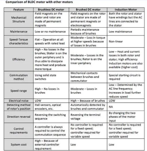
A Brushless DC motor is similar to that of Brushed DC motor, BLDC doesen't use brushes for commuting rather they are electronically commuted. In conventional DC motor brushes are used to transmit power to rotor as they turn to fixed magnetic field. In BLDC controller provide pulses of current to motor winding which control the speed of torque of synchronous motor.
Speed of BLDC is controlled by controlling the Input DC voltage/current . Higher the voltage more is the speed.
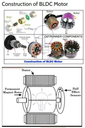
The main design design differnece between brushed and brushless is the replacememnt of mechenical commutator with an electric switch circuit.
BLDC motor consists of stator and rotor that generate magnetic field revolving at same frequency.
They are available in 3 models :-
- Single phase
- Two phase
- Three phase
STATOR :-
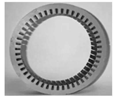
The structure of stator is almost similar to that of induction motor. It is made up of stacked steel laminations with axially cut slots for windings. The windings in BLDC are slightly different then other tradation motors,
ROTOR :-
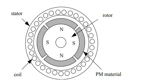
The rotor part of BLDC is made up of permanent magnet. It consits of number of poles between 2-8 with North & South placed altarnatively.
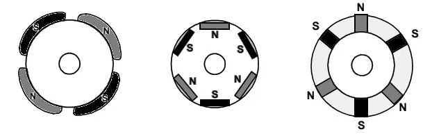
- In first case magnets are placed on the outer body of rotor.
- The second configuration is called magnetic embedded rotor, where permanent magnets are embedded into the core of the motor.
- In third case magnets are inserted into the iron core.
WORKING PRINCIPLE BLDC :-
In BLDC feedback is received by using multiple feedback sensor. In BLDC motor we mostly use Hall effect sensor, whenever rotor magnet pass through a Hall efect sensor it produces High or low level signal, which can be used to define the position of hall shaft. If the direction of magnetic field is reversed then voltage will be generated in reverse direction too.
ADVANTAGES OF BLDC :-
- No wear & tear
- High efficiency
- Better speed vs torque characterstics
- Long Life
- Less Noise
- Higher RPM
APPLICATION OF BLDC MOTOR :-
- Industrial engineering
- Servo Motors
- Actuators
- Drive Motors