Week-7 Challenge: DC Motor Control
1. A. Explain a MATLAB demo model named ‘Speed control of a DC motor using BJT H-bridge’.
POWER ELECTRONICS:
Power electronics is the application of solid-state electronics to the control and convertion of electric power.
In modernsystem the convertion is carried out with semi-conductor switches such as :
1. Diode
2. Thermistor and
3. Power Transistor like power MOSFET and IGBT.
In contrast to electronic systemconcerned with transmission and processing of signals and data, in power electronics substantial amount of electrical energies are processed.The power range is typically from tens of watts to several hundred watts.
In industry a common application is the variable speed drive(VSD).
A variable speed drive (also known as a VSD, variable frequency drive, VFD, adjustable speed drive, inverter, converter or simply, a drive) is a device which is used to control the speed or torque generated by an electric motor.The power range of VSDs starts from a few hundred watts and end at tens of megawatts.
SWITCHING TECHNIQUE :
Which is derived from power electronics to control the voltage and currect for electric motor.This avoids high amount of losses by replacing resistors with the power modules/switches.And these power modules are operated at high frequency where the rated battery voltage(Vbat) can be reduced to desire voltage by ON/OFF of module.
SWITCHING FREQUENCY:
It will be in such a way that it utilizes Vbat and switches low and high value of the voltage required for the motor.
The principle behind the power modules is not controlling the magnitude of the voltage but the duration of high and low voltage resulting the desired voltage level.
Duty ratio nothing but the ON/OFF switching frequency.
by changing the duty ratio of the power modules, we can vary the voltage from one level to another level.
Vavg=Vbat . d
Vavg = Average voltage required for the vehicle through motor.
d = Duty ratio
Vbat = Battery voltage.
POWER MODULES:
When it comes to EV application, controlling the speed of the motor mainly depends on controlling the current and voltage flow to the motor. To ensure a rotating field in the motor continuosly, flux has to be switched continuously by controlling the direction and timing of the current in to the coil.
In order to acheive this controllers/Inverters are used to adjust the voltae in the coil and to control the magnitude of the current.
PMW(Pulse width modulation):
It is the technique which incorporated in the power switches which alters the voltage level by lengthening or reducing the Pulse ON time.
power modules used in controllers/Inverters are Transistors,
A transistor is nothing but an semi-conductor device used to amplify or switch electronic signals and electrical power.It is composed of semiconduting materials usually with at least 3 terminals for conducting to an external circuit.A voltage or current applied to one pair of the transistor's terminals controls the current through another pair of terminals.Because the controlled(Output) power is higher than the controlled(input)power, a transistor can amplify a sgnal.
Power signal acts across Collector-Emitter(CE) when there is a control Signal across Base-Emitter(BE).
BI-POLAR JUNCTION TRANSISTOR(BJT) :
Which is a typical transistor that uses both electrons and holes as charge carriers.Unipolar transistor, such as field-effect transistor, use only one kind of charge carrier.A bipolar transistor allows a small current injected at one of its terminal to control a much large current flowing between two other terminals, making the device capable of amplification or switching.
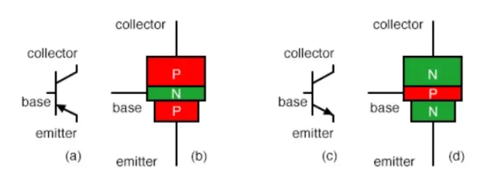
Bi-polar junction transistor current controlled current regulator.In other words the transistors restricts the amount of current passed according to a smaller, controlling current.The main current that is controlled goes from the collector to emitter, or from emitter to collector, depending on the type of transistor it is(N-P-N or P-N-P)respectively.The small current that controls the main current goes from the base to emitter or from emitter to base depends on the type of transistor.
MOSFET :
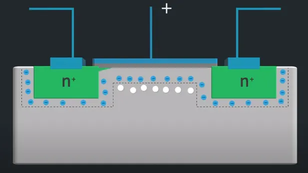
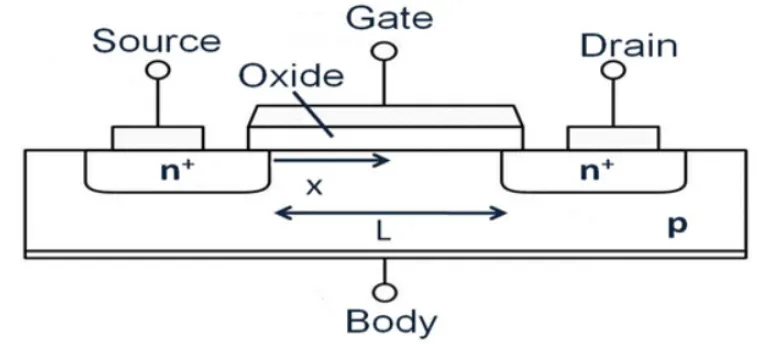
Metal oxide semiconductor field effect transistor is a semiconducting device which is widely used for switching and amplifying electronic signals in the electronic device.The MOSFET is a four terminal device with source(S), Gate(G), Body(B) and Drain(D) terminals.The body of the MOSFET is frequently connected to the source terminal so its making like a three terminal device like field effect transistor.
The MOSFET can function in two ways:
* Depletion mode:
When there is no voltage on the Gate, the channel shows its maximum conductance.As the voltage on the gate is either positive or negative the channel conductivity decrrease.
* Enhancement mode:
When there is no voltage on the gate the device doesntot conduct.More is the voltage on the gate, the better the device can conduct.
Working principle:
The aim of the MOSFET is to control the voltage and current between the Source and the Drain.It works almost as a switch.The working of MOSFET depends upon the MOS capacitor.The MOS capacitor is the main part of the MOSFET. The semiconductor surface which is present below the oxygen layer located between the source and drain terminal.It can be inverted from p-type to N-type by applying the positive or negative Gate voltage.When we apply the positive gate voltage the holes present below the oxide layer with a repulsive force and holes are pushed downwards with the substrate.The depletion region populated by the bound negative charges which are associated with the acceptor atom. The elctron reach the channel is formed. The positive voltage also attracts electrons from the n+ source and drain regions into the channel.Now if the voltage is applied between the source and drain, the current flow freely between the source and drain where the gate voltage controls the electrons in the channel. Instead of positive channel if we apply negative voltage, a hole channel will be formed under the oxide layer.
IGBT: Insulated Gate Bipolar Transistor
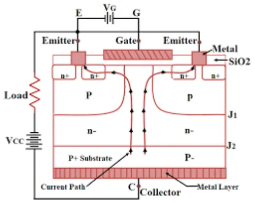
Is something cross between a conventional Bi-polar junction transistor and Field effect transistor.making it ideal as a semiconductor switching device.
The IGBT transistor taking up the best part of these two types of the transistor, the high input impedance and high switching speed of a MOSFET with the low saturation voltage of a bipolar transistor, and combines them together to produce another type of transistor switcing device that is capable of handling large collector-emitter current with virtually zero gate current drive.
IGBT structure:
1. A. Explain a MATLAB demo model named ‘Speed control of a DC motor using BJT H-bridge’.
B. Comment on the armature current shoot-up from the scope results.
Power H-bridge:
Simscape Electrical Documentation - MathWorks India
https://in.mathworks.com/help/physmod/sps/examples/speed-control-of-a-dc-motor-using-bjt-h-bridge
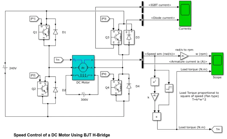
The Bipolar junction transistor (BJT) when used for power switching applications, operates as an IGBT. When it is conducting (BJT operates in the saturated region), a forward voltage Vf is developed between collector and emitter(in the range of 1V).Therefore the IGBT block can be used for BJT device.
The IGBT block doesnot simulate the gate current controlling the BJT or IGBT.The switch is controlled by the Simulink signal.The DC motor uses the pre-set mode(5HP 24V 1750RPM).
It simulates the fan type load(where load torque is proportional to square of speed). The armature mean voltage can be varied from 0 to 240V when the duty cycle(specified in the pulse generator block) is varied from 0 to 100%.
The H-bridge consist of four BJT diode pairs(BJT simulated by IGBT models).
Two transistors are switched simultaneously:
Q1 and Q4 are fired, a positive voltage is applied to the motor and diodes D2-D3 operates as free wheeling diodes.
When Q2 and Q3 are fired , a negative voltage is applied to the motor and diodes D1 and D4 operates as free wheeling diodes.
Model & spec:
As of mentioned from the block diagram ;
Power= 5Hp
Rated voltage = 240V
Rated speed = 1750rpm
where the motor starts in a positive direction with a duty cycle of 75%
a DC voltage of 180V
At t=0.5sec, the armature voltage is suddenly reversed and the motor runs in the negative direction.
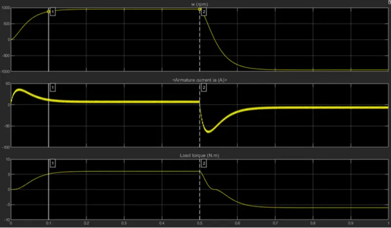
From the above figure states that the torque of 6Nm is applied to the motor initially at the time of 0.5sec where the direction of rotation is reversed and a negative torque of same magnitude can be observed.
Motor speed against time : speed is proportional to the applied load torque.
Initial spike of current is observed in the armature.
In motor , armature current is given by
I =(V-E)/ R
I depends upon E and R, where V is kept constant.When motor starts its speed remains Zero.E is also remains zero (Back Emf is proportional to speed of the armature).
Thus the initial armature current;
I=(V-0)/R
=V/R
Since the armature resistance of the motor is very small, generally less than one ohms thats y the starting current is very large.
As the motor speed increses the back emf increases and the difference in V-E keeps on decreasing.Thus result in the gradual decrease of armature current until the motor attains its stable rated speed.Under this condition the armature current reaches its desired rated value.
Another shoot up can be observed in the armature current when the motor changes direction from forward to reverse.
Inorder to avoid this duty ratio can be optimized.
where thhe duty ratio changes from 75% to 45%.
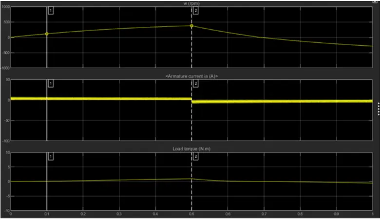
by reducing the duty ratio the armature current shoot can be completely optimized.
* But there will be considerable fall in the load torque and speed.
* No load torque of the motor can be reduced from 6nm to 2nm.
* No load speed is reduced from 900rpm to 400rpm.
By reducing the duty ratio of the power module we can ultimately reduce the effect of shooting armature current but reduces the supply voltage into the motor and results in the reduction of the rated speed and torque of the motor.
2. Comparing‘The Four-Quadrant Chopper DC Drive (DC7) block’with the H-bridge model. Develop a 2-quadrant chopper using simulink & explain the working of the same with the relevant results. (Refer to article - Multiquadrant operation of motor )
The four quadrant chopped DC drive(DC7) block represents a four-quadrant DC supplied chopper drive for DC motors.This drive features a closed loop speed control with four quadrant operation.The speed control loop outputs the reference armature current of the machine.Using a PI current controller.The chopper duty cycle corresponds to the commanded armature current is derived.This duty cycle is then compared with the sawtooth carrier signal to obtain the required PMW signals for the chopper.
The main advantages for this drive is compared with the DC drives that it can operate in all four quadrants (Forward motoring, reverse regeneration, reerse motoring and forward regeneration)In addition due to the use of high switching frequencyDC-DC converterr, a lower armature current ripple(Compared to thyrister based DC drive) is obtained.However four switching devices are required,which increases the complexity of the drive system.
Example:
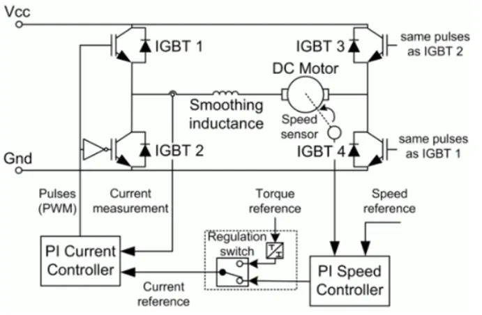
The armature voltage is provided by the IGBT converter controlled by two PI regulators.The converter is fed by a 515V DC bus obtained by rectification of a 380V AC 50Hz voltage source.In order to limit the DC bus voltage during dynamic braking mode, a brake chopper have been added between the diode rectifier and the DC7 block.
The first regulator is a speed regulator, followed by a current regulator.The speed regulator outputs the armature current reference used by the current controller in order to obtain the electromagnetic torque needed to reach the desired speed.The speed reference change rate follows acceleration and deceleration ramps in order to avoid sudden reference changes that could cause armature over current and destabilize the system.
The current regulator controls the armature current by computing the appropriate duty ratio of the 5Hz pulses of th four IGBT device(pulse Width Modulation).For proper system behaviour the instantaneous pulse value of IGBT device 1 and 4 are opposite to those of IGBT device 2 and 3.This generates the average armature voltage neede to obtain the desired armature current.In order to limit the amplitude of the current oscillation, a smoothing inductance is placed in series with the armature circuit.
Comparison with H-Bridge models:
The machine is seperately excited with a constant DC field voltage source.There is thus no field voltage control.By default, the field current is set to its steady state values when a simulation is started.
The armature voltage is provided by an IGBT converter controlled by an two PI regulators.The converter is fed by an constant DC voltage source.Armature current oscillations are reduced by an smoothing inductance connected in series with the armature current.
The model is discrete.Good simulation results have been obtained from an 1mu-sec time step.
In order to simulate a digital control device, the control system has two sampling time;
* The speed control sampling time
* The current control sampling time.
The speed control sampling time has to be an multiplication of an current controlling sampling time.The latter samping time has to be a multiple of the simulation time step.
The DC7 is capable of operating in all 4 quadrants of motoring operation.They are forward braking, forward motoring,reverse motoring and reverse braking.A motor operates in two models- Motoring and braking.
A motor drive is capable of operating in both direction of rotation and of producing both motoring and regeneration is called four-quadrant variable speed drive.
In motoring mode, the machine works as a motor and convert the electrical energy into mechanical energy, supporting its motion.In braking mode the machine works as a generator, in which it converts mechanical energy into electrical energy and as a result it opposes the motion.The motor can work in both forward and reverse direction,i.e in motoring and braking operation.
The four quadrant operation of drives:
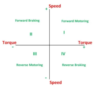
So in the I quadrant power development is positive and the machine is working as a motor supplying mechanical energy.The first quadrant operating is called forward motoring.
The II quadrant is called as a Braking, in this quadrant the motor direction of rotation is positive and the torque is negative and thus the machine operates as a generator developing a negative torque which opposes the motion. The kinetic energy of the rotating part is available as electrical energy which may be supplied back to the mains.In dynamic braking the energy is dissipated in the resistance.
In the III quadrant operation is known as reverse motoring.The motor works in the reverse direction.Both the speed and torque having negative values while the power is positive.
In the IV quadrant the torque is positive and the speed is negative.This quadrant corresponds to braking in the reverse motoring mode.
Simulation plot with 200 HP DC Drive:
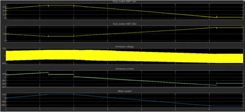
The motor is coupled to a linear load, which means that the mechanical torque of the load is proportional to the speed.
The armature current follows the the current reference very well, with fast response time and small ripples.
When the motor reaches 0 rom and the load torque reverses and becomes negative.The negative current now produces an accelerating electromagnetic torque to allow the motor to follow the negative speed ramp.
Four quadrant DC Drive uses reference load and speed to cope up with the motor direction of rotation and supply current.The current shootups are minimized here when compared that of with H-Bridge model.
3. Explain in a brief about operation of BLDC motor.
A brushless DC electric motor (BLDC motor or BL motor), also known as an electronically commutated motor (ECM or EC motor) or synchronous DC motor, is a synchronous motor using a direct current (DC) electric power supply.
It uses an electronic closed loop controller to switch DC currents to the motor windings producing magnetic fields which effectively rotate in space and which the permanent magnet rotor follows. The controller adjusts the phase and amplitude of the DC current pulses to control the speed and torque of the motor.
This control system is an alternative to the mechanical commutator (brushes) used in many conventional electric motors. The construction of a brushless motor system is typically similar to a permanent magnet synchronous motor (PMSM), but can also be a switched reluctance motor, or an induction (asynchronous) motor. They may also use neodymium magnets and be outrunners (the stator is surrounded by the rotor), inrunners (the rotor is surrounded by the stator), or axial (the rotor and stator are flat and parallel). The advantages of a brushless motor over brushed motors are high power-to-weight ratio, high speed, nearly instantaneous control of speed (rpm) and torque, high efficiency, and low maintenance.
Brushless motors find applications in such places as computer peripherals (disk drives, printers), hand-held power tools, and vehicles ranging from model aircraft to automobiles. In modern washing machines, brushless DC motors have allowed replacement of rubber belts and gearboxes by a direct-drive design.
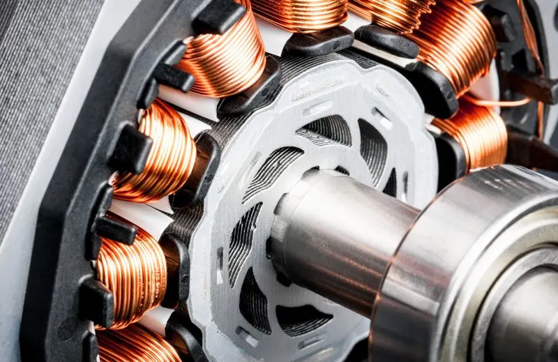
Permanent magnet brushless DC motor for new energy electric vehicles can realize many advantages such as low energy consumption, high efficiency, large torque, fast start, low noise, long life, zero emission and so on. It can not only improve the range of the vehicle, but also prolong the service life of the battery.
Diagramatical representation working principal of BLDC motor:
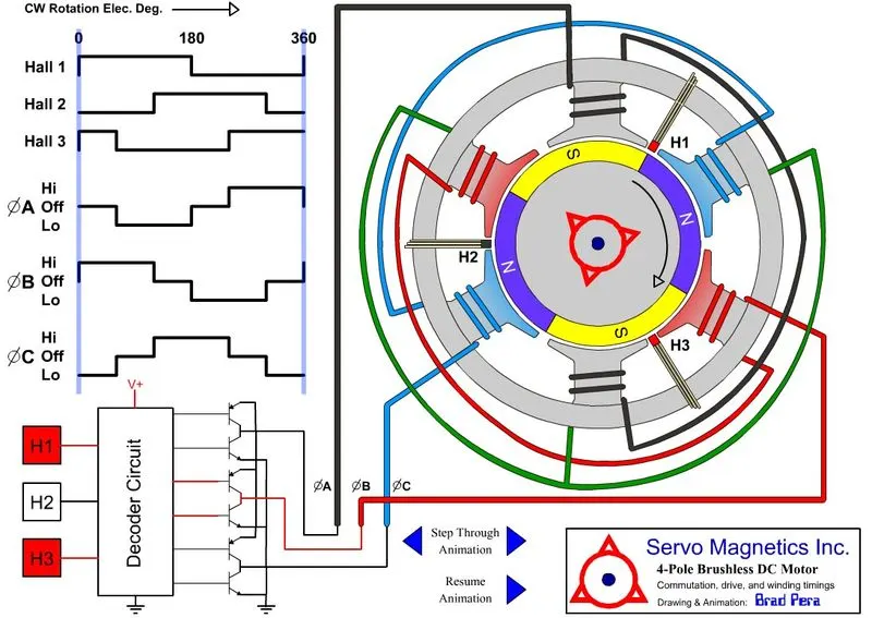
stage by stage working strategy of a brushless DC motor.
In a typical DC motor, there are permanent magnets on the outside and a spinning armature on the inside. The permanent magnets are stationary, so they are called the stator. The armature rotates, so it is called the rotor.
The armature contains an electromagnet. When you run electricity into this electromagnet, it creates a magnetic field in the armature that attracts and repels the magnets in the stator. So the armature spins through 180 degrees. To keep it spinning, you have to change the poles of the electromagnet. The brushes handle this change in polarity. They make contact with two spinning electrodes attached to the armature and flip the magnetic polarity of the electromagnet as it spins.
This setup works and is simple and cheap to manufacture, but it has a lot of problems:
* The brushes eventually wear out.
* Because the brushes are making/breaking connections, you get sparking and electrical noi
* The brushes limit the maximum speed of the motor.
* Having the electromagnet in the center of the motor makes it harder to cool.
* The use of brushes puts a limit on how many poles the armature can have.
With the advent of cheap computers and power transistor, it became possible to "turn the motor inside out" and eliminate the brushes. In a brushless DC motor (BLDC), you put the permanent magnets on the rotor and you move the electromagnets to the stator. Then you use a computer (connected to high-power transistors) to charge up the electromagnets as the shaft turns.This system has all sorts of advantages.
*Because a computer controls the motor instead of mechanical brushes, it's more precise. The computer can also factor the speed of the motor into the equation. This makes brushless motors more efficient.
* There is no sparking and much less electrical noise.
* There are no brushes to wear out.
* With the electromagnets on the stator, they are very easy to cool.
* You can have a lot of electromagnets on the stator for more precise control.
The only disadvantage of a brushless motor is its higher initial cost, but you can often recover that cost through the greater efficiency over the life of the motor.