Week-7 Challenge: DC Motor Control
1a) Explain a MATLAB demo model named ‘Speed control of a DC motor using BJT H-bridge’.
Source link https://in.mathworks.com/help/physmod/sps/ug/speed-control-of-a-dc-motor-using-bjt-h-bridge.html
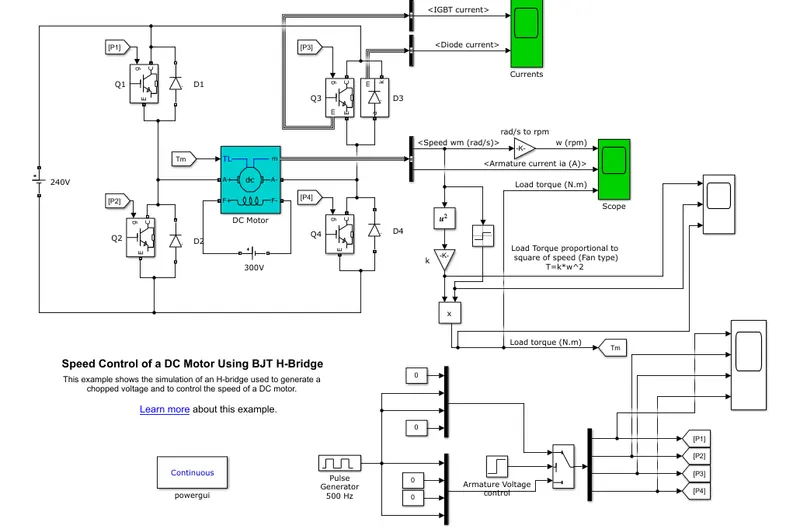
Figure 1
Figure 1 shows the simulink of 'Speed control of a DC Motor using BJT H-bridge'
the heart of this simulink is DC motor
DC motor is a electric machine that converts electrical energy into mechanical energy
The principle of motor is based of Faradays 2nd law ' whenever current carrying conductor is placed in a magnetic field, it experiences a force'.
armature voltage = 240 volts
field voltage = 300 volts
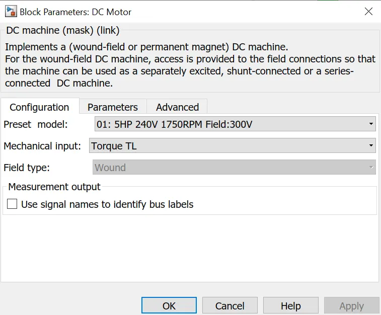
Figure 2
Figure 2 shows the specifications of DC motor
powew rating = 5 HP
input armature voltage = 240 volts
rated speed = 1750 rpm
input field voltage = 300 volts
In figure 1, H-Bridge is used to control of DC motor. In H-bridge there are 4 BJT alond 4 Diodes are present
500 MHz pulse generator is used to operate Q1,Q2,Q3 & Q4
switchs Q1&Q4 -> ON & Q2&Q3 -> OFF in forward motoring
switches Q2&Q3 -> ON & Q1&Q4 -> OFF in reverse motoring
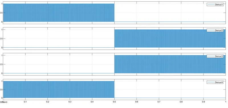
Figure 3
Figure 3 shows the pulses to Q1,Q2,Q3&Q4
from Figure 3
in 0 to 0.5 seconds 'switchs Q1&Q4 -> ON & Q2&Q3 -> OFF' as gate signal ON for Q1&Q4 and gate signal OFF for Q2&Q3. This results current path is
240 volts -> Q1 -> Motor -> Q4 -> 240 volts
In 0.5 to 1 seconds 'switches Q2&Q3 -> ON & Q1&Q4 -> OFF' as gate signal ON for Q2&Q3 and gate signal OFF for Q1&Q4. This results current path is
240 volts -> Q3 -> Motor -> Q2 -> 240 volts
From the above explanation motor direction is forward during 0 to 0.5 seconds and reverse > 0.5 seconds.
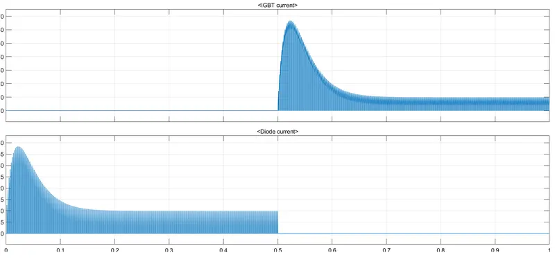
Figure 4
Figure 4 shows the Diode and BJT current of Q3
In this Diode is used to stop current flow in reverse direction
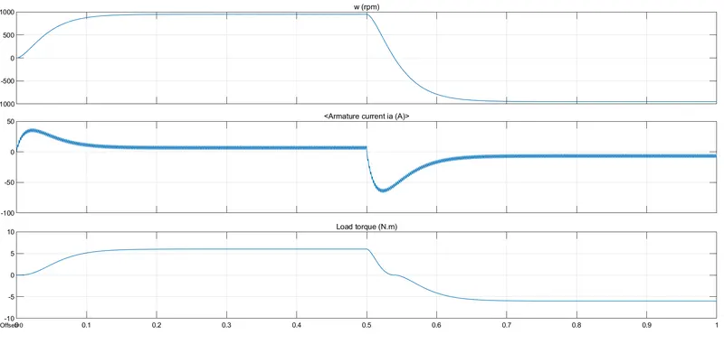
Figure 5
Figure 5 shows the speed,Armature current and load torque of DC motor
as we discussed that from 0.5 seconds as current direction reverse, speed and torque are also reverse.
1B) Comment on the armature current shoot-up from the scope results
From the figure 5 inorder to start motor we required high amount of current.
And also during reversal speed of motor there is a shoot-up of current, the reason behind is switching action. From Figure 4 we can say that during switching action high amount of power is going to loss.
During switching OFF condition , there is a gradual decrease of current and gradual increase of voltage. The product of voltage and current gives power loss.
During Switching ON condition, there is a gradual decrease of voltage and gradual increase of current. here also product of voltage and current gives power loss.
1C) Refer to the help section of ‘The Four-Quadrant Chopper DC Drive (DC7) block’. Compare it with the H-bridge model.
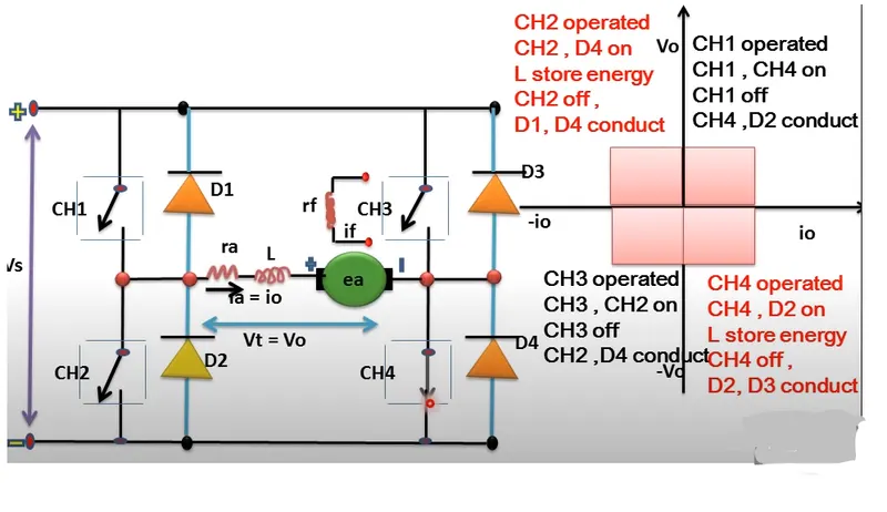
Figure 6
Figure 6 shoes the operation of 4 quadrant operation
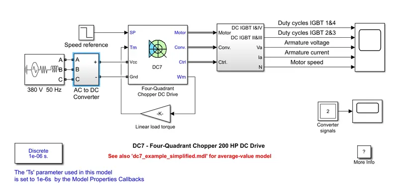
Figure 7
Figure 7 shoes the simulink diagram of Four-Quadrant chopper 200 HP DC drive
motor capacity 200 HP
field voltage 150 volts
AC voltage is 380 volts 50 Hz
DC voltage is 515 volts
To limit the DC bus voltage during dynamic braking mode, a braking chopper has been added between the diode rectifier and the DC7 block.
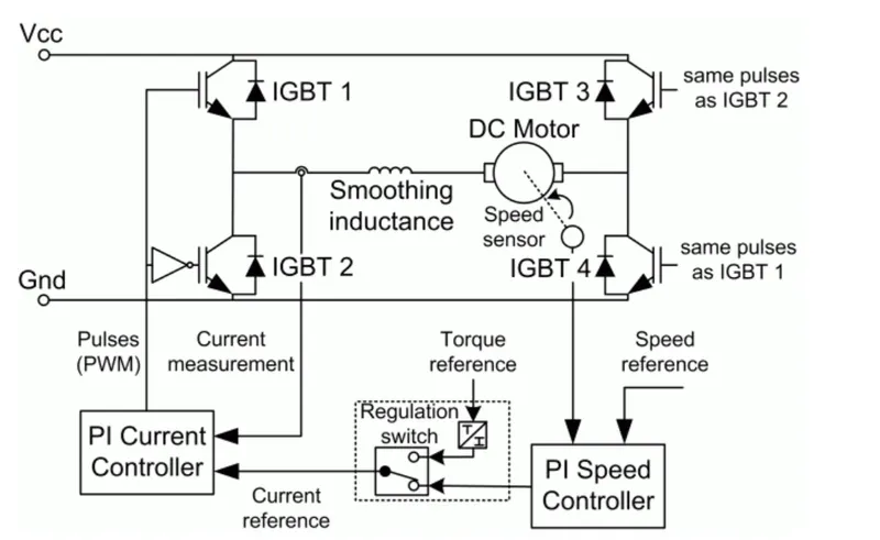
Figure 8
Figure 8 shows the four-quadrant chopper DC drive
The speed control loop outputs the reference armature current of the machine. Using a PI current controller, the chopper duty cycle corresponding to the commanded armature current is derived.
This duty cycle is then compared with a sawtooth carrier signal to obtain the required PWM signals for the chopper.
This chopper can operate in all 4 quadrant
The machine is separately excited with a constant DC field voltage source. There is thus no field voltage control. The armature voltage is provided by an IGBT converter controlled by two PI regulators.
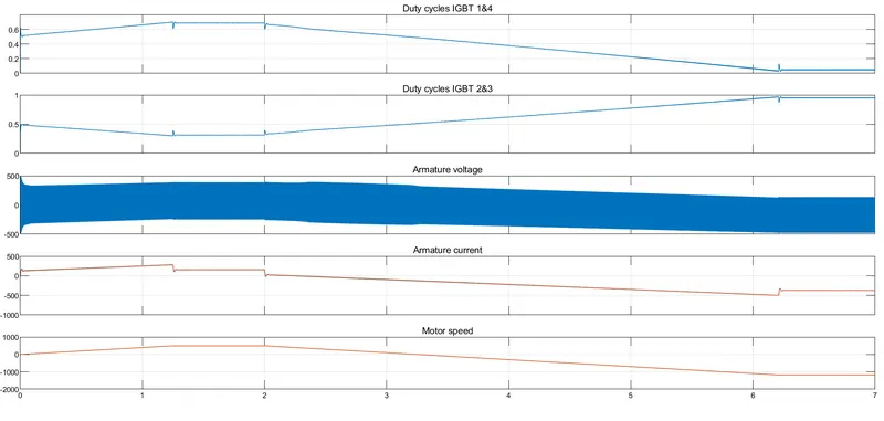
Figure 9
Figure 9 shows thr simulation results of Four-Quadrant chopper 200 HP DC drive (figure 7)
The speed reference is set at 500 rpm at t = 0 s. Observe that the motor speed follows the reference ramp accurately and reaches steady state around t = 1.3 s.
At t = 2 s, speed reference drops to -1184 rpm. The current reference decreases to reduce the electromagnetic torque and causes the motor to decelerate with the help of the load torque.
At t = 2.2 s, the current reverses in order to produce a braking electromagnetic torque (dynamic braking mode). This causes the DC bus voltage to increase.
At t = 3.25 s, the motor reaches 0 rpm and the load torque reverses and becomes negative. The negative current now produces an accelerating electromagnetic torque to allow the motor to follow the negative speed ramp (-400 rpm/s). At t = 6.3 s, the speed reaches -1184 rpm and stabilizes around its reference.
2. Develop a 2-quadrant chopper using simulink & explain the working of the same with the relevant results. (Refer to article - Multiquadrant operation of motor )
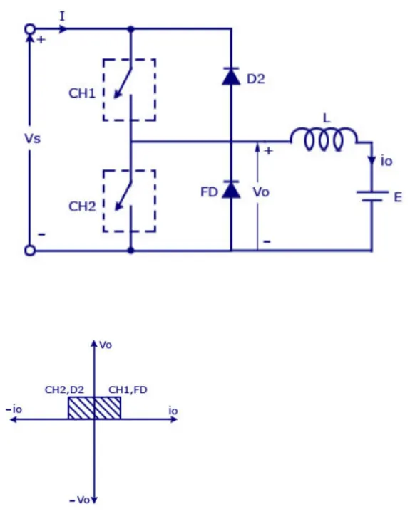
Figure 10
Figure 10 shows that block diagram of two quadrant DC chopper
In this two quadrant of Q1 and Q2 region
in Q1 voltage and current is positive
in Q2 voltage is positive and current is negative

Figure 11
Figure 11 shows the simulink diagram of Q1 and Q2 chopper
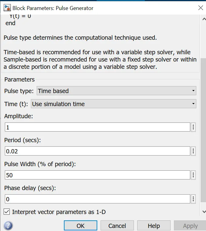
Figure 12
Figure 12 shows that 50 Hz frequence of pulse generatot with 50 % duty cycle and time period = 0.02 seconds
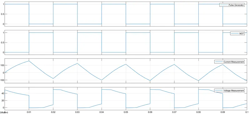
Figure 13
Figure 13 shows that result of Q1 and Q2 quadrant chopper
graph 1 shows pulse generator with time period 0.02 seconds
graph 2 shows not gate to graph 1
graph 3 shows that current through load
graph 4 shows that voltage across load
Time period from 0 to 0.01 seconds voltage and current is positive i.e. chopper working in Q1 region
Time period at 0.02 seconds current is negative and voltage is positive i.e. chopper working in Q2 region
3. Explain in a brief about operation of BLDC motor.
BLDC motor works on the principle similar to that of a conventional DC motor, i.e., the Lorentz force law which states that whenever a current carrying conductor placed in a magnetic field it experiences a force. As a consequence of reaction force, the magnet will experience an equal and opposite force. In case BLDC motor, the current carrying conductor is stationary while the permanent magnet moves.
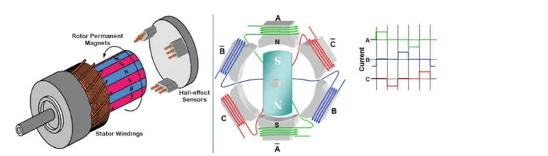
Figure 14
Figure 14 shows the construction of BLDC motor
When the stator coils get a supply from source, it becomes electromagnet and starts producing the uniform field in the air gap. Though the source of supply is DC, switching makes to generate an AC voltage waveform with trapezoidal shape. Due to the force of interaction between electromagnet stator and permanent magnet rotor, the rotor continues to rotate.With the switching of windings as High and Low signals, corresponding winding energized as North and South poles. The permanent magnet rotor with North and South poles align with stator poles which causes the motor to rotate.