Week-7 Challenge: DC Motor Control
Aim:
1. A. Explain a MATLAB demo model named ‘Speed control of a DC motor using BJT H-bridge’.
B. Comment on the armature current shoot-up from the scope results.
C. Refer to the help section of ‘The Four-Quadrant Chopper DC Drive (DC7) block’. Compare it with the H-bridge model.
2. Develop a 2-quadrant chopper using simulink & explain the working of the same with the relevant result.
3. Explain in a brief about operation of BLDC motor.
1.
The Bipolar Junction Transistor (BJT) when used for power switching applications, operates as an IGBT. When it is conducting (BJT operating in the saturated region), a forward voltage Vf is developed between collector and emitter (in the range of 1 V). Therefore, the IGBT block can be used to model the BJT device.
The IGBT block does not simulate the gate current controlling the BJT or IGBT. The switch is controlled by a Simulink® signal (1/0). The DC motor uses the preset model (5 HP 24V 1750 rpm). It simulates a fan type load (where Load torque is proportional to square of speed). The armature mean voltage can be varied from 0 to 240 V when the duty cycle (specified in the Pulse Generator block) is varied from 0 to 100%.
The H-bridge consists of four BJT/Diode pairs (BJT simulated by IGBT models). Two transistors are switched simultaneously: Q1 and Q4 or Q2 and Q3. When Q1 and Q4 are fired, a positive voltage is applied to the motor and diodes D2-D3 operate as free-wheeling diodes when Q1 and Q4 are switched off. When Q2 and Q3 are fired, a negative voltage is applied to the motor and diodes D1-D4 operate as free-wheeling diodes when Q2 and Q3 are switched off.
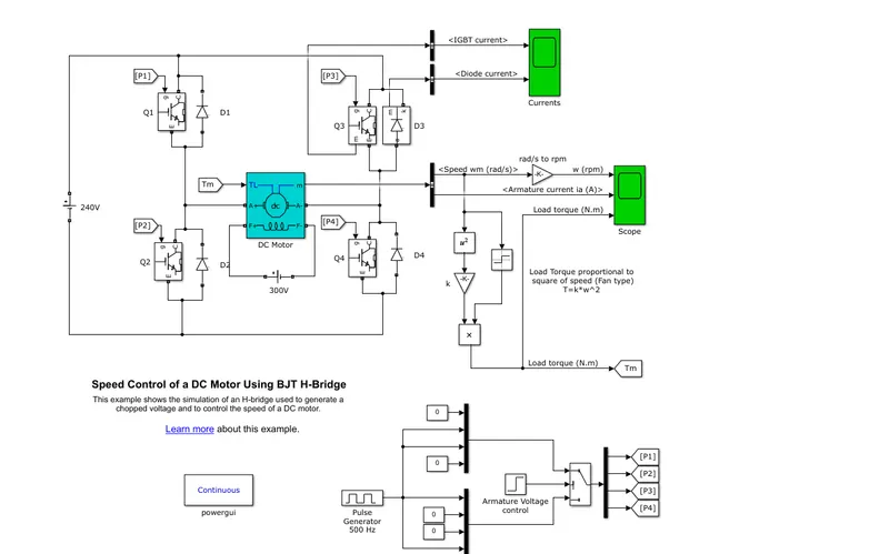
Case 1: pluse width 75
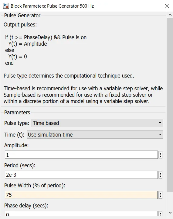
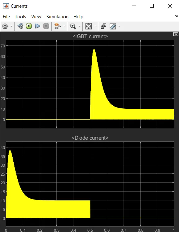
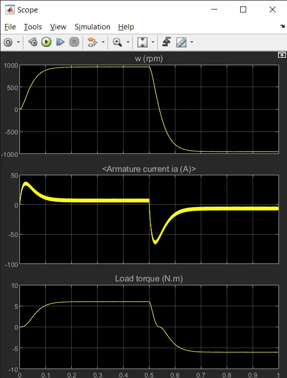
Case2:pluse width 45
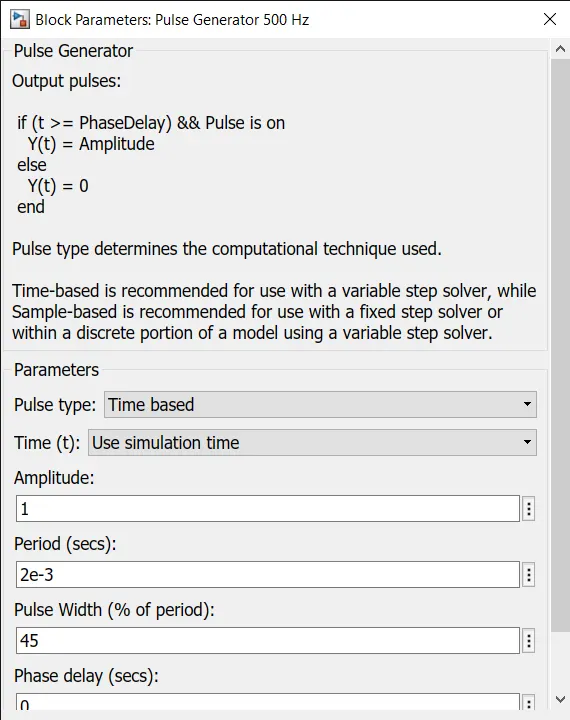
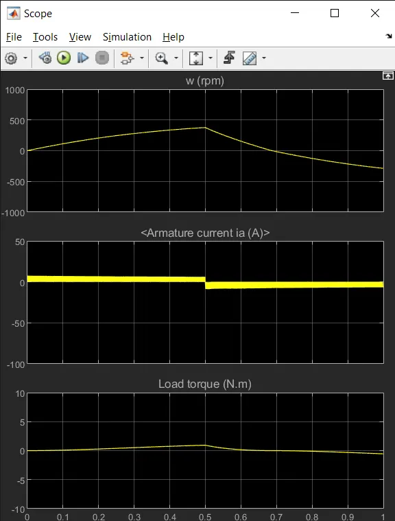
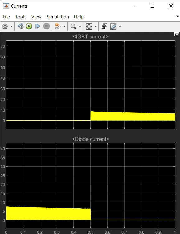
We can observe from the above graphs if we increase the pluse width the all the parameters in the graph increases and when we decrease the pluse width the rpm and currents also decreases.
The Four-Quadrant Chopper DC Drive (DC7) block
The 200 HP DC motor is separately excited with a constant 150 V DC field voltage source. The armature voltage is provided by an IGBT converter controlled by two PI regulators. The converter is fed by a 515 V DC bus obtained by rectification of a 380 V AC 50 Hz voltage source. In order to limit the DC bus voltage during dynamic braking mode, a braking chopper has been added between the diode rectifier and the DC7 block.
The first regulator is a speed regulator, followed by a current regulator. The speed regulator outputs the armature current reference (in p.u.) used by the current controller in order to obtain the electromagnetic torque needed to reach the desired speed. The speed reference change rate follows acceleration and deceleration ramps in order to avoid sudden reference changes that could cause armature over-current and destabilize the system. The current regulator controls the armature current by computing the appropriate duty ratios of the 5 kHz pulses of the four IGBT devices (Pulse Width Modulation). For proper system behaviour, the instantaneous pulse values of IGBT devices 1 and 4 are opposite to those of IGBT devices 2 and 3. This generates the average armature voltage needed to obtain the desired armature current. In order to limit the amplitude of the current oscillations, a smoothing inductance is placed in series with the armature circuit.
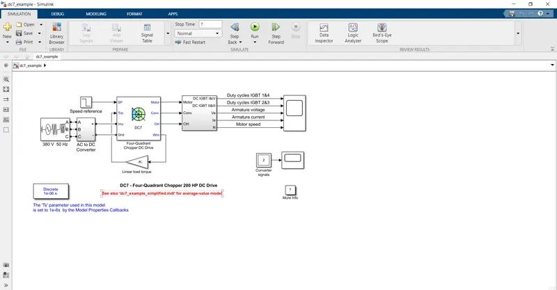
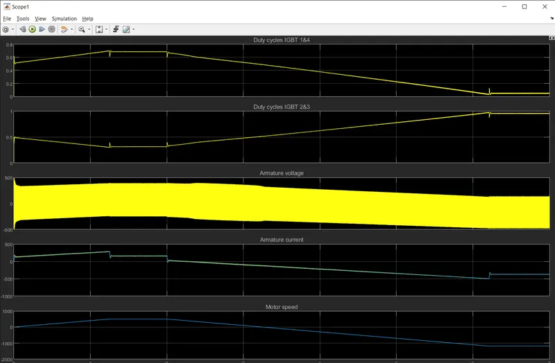
By comparing the The Four-Quadrant Chopper DC Drive (DC7) block with BJT h-bridge
The model has certain working operations and some applications.
In the H-bridge we need to change the polarity which turns into opposite direction
In the The Chopper we need to interrupt one signal under control and voltage
In H-bridge regenertive braking is not possible in The Four-Quadrant Chopper block it is possible
The H-bridge is mainly used for robotic operations and the chopper is mainly used in motor control.
2.
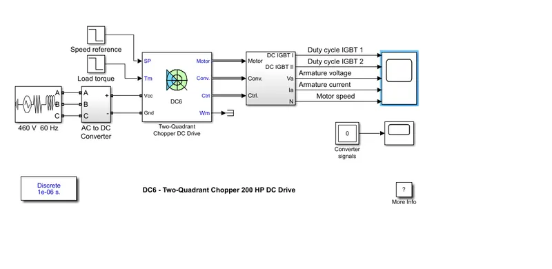
2-quadrant chopper
The 200 HP DC motor is separately excited with a constant 150 V DC field voltage source. The armature voltage is provided by an IGBT buck-boost converter controlled by two PI regulators. The buck-boost converter is fed by a 630 V DC bus obtained by rectification of a 460 V AC 60 Hz voltage source. In order to limit the DC bus voltage during dynamic braking mode, a braking chopper has been added between the diode rectifier and the DC6 block.
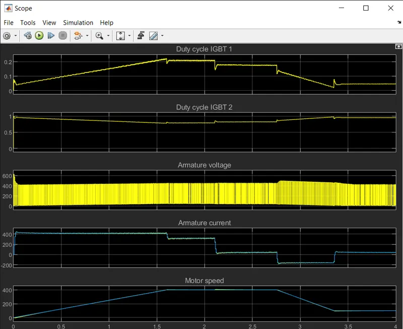
The first regulator is a speed regulator, followed by a current regulator. The speed regulator outputs the armature current reference (in p.u.) used by the current controller in order to obtain the electromagnetic torque needed to reach the desired speed. The speed reference change rate follows acceleration and deceleration ramps in order to avoid sudden reference changes that could cause armature over-current and destabilize the system. The current regulator controls the armature current by computing the appropriate duty ratios of the 5 kHz pulses of the two IGBT devices (Pulse Width Modulation).For proper system behaviour, the two IGBT devices have opposite instantaneous pulse values.This generates the average armature voltage needed to obtain the desired armature current. In order to limit the amplitude of the current oscillations, a smoothing inductance is placed in series with the armature circuit.
3.BLDC motor.
A brushless DC electric motor , also known as an electronically commutated motor or synchronous DC motor, is synchronous DC motor a using a dirrect current electric power supply. It uses an electronic closed loop controller to switch DC currents to the motor windings producing magnetic fields which effectively rotate in space and which the permanent magnet rotor follows. The controller adjusts the phase and amplitude of the DC current pulses to control the speed and torque of the motor. This control system is an alternative to the mechanical commutator (brushes) used in many conventional electric motors.
The construction of a brushless motor system is typically similar to a permanent magnent synchronous(PMSM), but can also be a switched reluctance motor , or an induction motor . They may also use neodymium magnents and be outrunners(the stator is surrounded by the rotor), inrunners(the rotor is surrounded by the stator), or axial (the rotor and stator are flat and parallel).
Brush commutator:
In brushed motors this is done with a rotary switch on the motor's shaft called a commutator It consists of a rotating cylinder divided into multiple metal contact segments on the rotor. The segments are connected to conductor windings on the rotor. Two or more stationary contacts called brushes, made of a soft conductor like graphite, press against the commutator, making sliding electrical contact with successive segments as the rotor turns. The brushes selectively provide electric current to the windings. As the rotor rotates, the commutator selects different windings and the directional current is applied to a given winding such that the rotor's magnetic field remains misaligned with the stator and creates a torque in one direction.
The commutator has disadvantages that has led to a decline in use of brushed motors. These disadvantages are
- The friction of the brushes sliding along the rotating commutator segments causes power losses that can be significant in a low power motor.
- The soft brush material wears down due to friction, creating dust, and eventually the brushes must be replaced. This makes commutated motors unsuitable for low particulate or sealed applications like hard disk motors, and for applications that require maintenance-free operation.
- The electrical resistance of the sliding brush contact causes a voltage drop in the motor circuit called brush drop which consumes energy.