Week-7 Challenge: DC Motor Control
1)
1.1
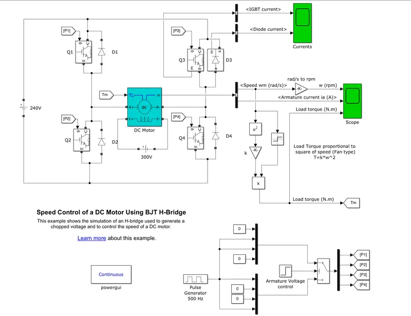
The Bipolar Junction Transistor (BJT) when used for power switching applications, operates as an IGBT. When it is conducting (BJT operating in the saturated region), a forward voltage Vf is developed between collector and emitter (in the range of 1 V). Therefore, the IGBT block can be used to model the BJT device.
The IGBT block does not simulate the gate current controlling the BJT or IGBT. The switch is controlled by a Simulink signal (1/0). The DC motor uses the preset model (5 HP 24V 1750 rpm). It simulates a fan type load (where Load torque is proportional to square of speed). The armature mean voltage can be varied from 0 to 240 V when the duty cycle (specified in the Pulse Generator block) is varied from 0 to 100%.
working
- The H-bridge consists of four BJT/Diode pairs (BJT simulated by IGBT models).
- Two transistors are switched simultaneously: Q1 and Q4 or Q2 and Q3.
- When Q1 and Q4 are fired, a positive voltage is applied to the motor and diodes D2-D3 operate as free-wheeling diodes when Q1 and Q4 are switched off.
- When Q2 and Q3 are fired, a negative voltage is applied to the motor and diodes D1-D4 operate as free-wheeling diodes when Q2 and Q3 are switched off.
Simulation
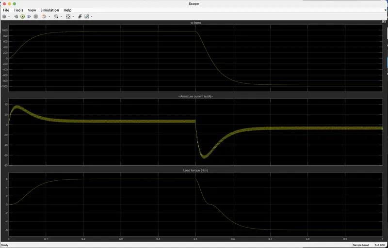
The motor starts in the positive direction with a duty cycle of 75% (mean DC voltage of 180V). At t= 0.5 sec., the armature voltage is suddenly reversed and the motor runs in the negative direction.
'Scope' shows motor speed, armature current and load torque and 'Currents' shows currents flowing in BJT Q3 and diode D3.
1.2
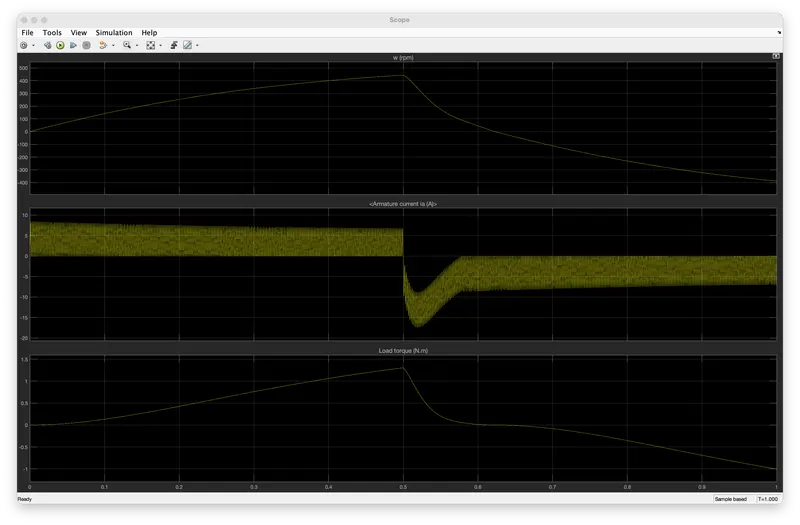
Due to duty cycle the current deviation is observed in the result, when the duty cycle is changed to 50 from 75 we can observe that the amount of deviation is also reduced.
1.3
The Four-Quadrant Chopper DC Drive (DC7) block represents a four-quadrant, DC-supplied, chopper (or DC-DC PWM converter) drive for DC motors. This drive features closed-loop speed control with four-quadrant operation. The speed control loop outputs the reference armature current of the machine. Using a PI current controller, the chopper duty cycle corresponding to the commanded armature current is derived.
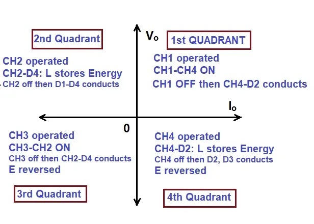
the main advantage of this drive, compared with other DC drives, is that it can operate in all four quadrants (forward motoring, reverse regeneration, reverse motoring, and forward regeneration).
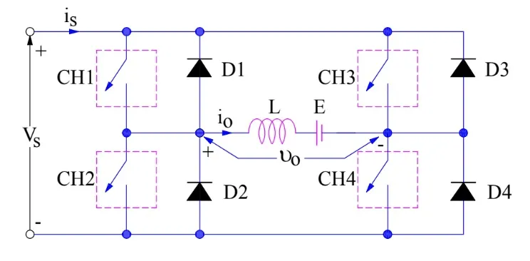
Forward motoring mode (first quadrant)
-
ch4 is kept on, ch3 is kept off and ch1 is operated.
- With CH! And CH4 both ON, armature voltage Vo = Vs and armature control Io begins flow. Here both Vo and Io are positive giving first quadrant operation.
- when CH1 is turned off, positive current freewheels through CH4 and D2. In this manner, Vo, Io can be controlled in this first quadrant, and operation gives forward motoring mode.
Forward regenerative braking mode (second quadrant)
- Here CH2 is operated and CH1, CH3 and CH4 are kept off. With CH4 on, reverse or negative current flows through L, CH2, D4 and armature.
- During the operation time of CH2, the armature inductance ‘L’ stores energy during the time CH2 is on.
-
When CH2 is turned off, current is fed back to source through diodes D1, D4 .As the Vs is positive and Ia is negative, it is a second quadrant operation gives forward braking mode. In that power is fed back from armature to source.
Reverse motoring mode (third quadrant)
-
CH1 is kept off, CH2 is kept on and CH3 is operated
-
Here polarity of back EMF Eb is reversed
- With CH3 is on, armature gets connected to source V. so that both Vo , Io are negative, leading to third quadrant operation.
-
When CH3 is turned off,negative current free wheels through CH2,D4. In this manner only Vo and Io can be controlled in the third quadrant.
Reverse regenerative braking mode (forth quadrant)
- CH4 is operated and other devices kept off
-
Polarity of back emf Eb is reversed
-
With S4 on, positive current flows through CH4,D2,Lo and armature. During this operation energy is stored in armature inductor (Lo)
- When CH4 is turned off, current is fed back to source through diodes D2, D3.Here armature voltage Vo is negative, but Io is positive, leading to the chopper drive operation in the fourth quadrant. Also power is fed back from armature to source.
2)
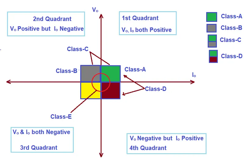
Type -C chopper or Two-quadrant type-A Chopper
Can operate in both the first as well as second quadrant. During the first quadrant operation, it acts a step-down chopper while in second quadrant it behaves as step-up chopper. Basically, Class-C is obtained by parallelly connecting Class-A & Class-B chopper.
Type D Chopper or Two-Quadrant Type –B Chopper
can operate in first and fourth quadrant. In this chopper, the direction of load current doesn’t reverse rather the average DC output voltage (Vo) may reverse. For in-depth understanding of how the polarity of output voltage reverses. Power can either be transferred from source to load or load to source. This chopper is also known as Two Quadrant Class-B chopper.