Week-7 Challenge: DC Motor Control
Aim:
- Explain and Run MATLAB demo ‘Speed control of a DC motor using BJT-H Bridge’. The armature current shoot-up from the scope results are to be observed.
- Refer to the help section of ‘The Four-Quadrant Chopper DC Drive (DC7) block’. Compare it with the H-Bridge model.
- Develop a 2-quadrant chopper using Simulink & explain the working of the same with the relevant results.
- Explain about BLDC Motor
Theory:
BJT-H Bridge:
The Bipolar Junction Transistor (BJT) when used for power switching applications, operates as an IGBT. When it is conducting (BJT operating in the saturated region), a forward voltage Vf is developed between collector and emitter (in the range of 1 V). Therefore, the IGBT block can be used to model the BJT device.
The IGBT block does not simulate the gate current controlling the BJT or IGBT. The switch is controlled by a Simulink® signal (1/0). The DC motor uses the pre-set model (5 HP 24V 1750 rpm). It simulates a fan-type load (where Load torque is proportional to the square of speed). The armature's mean voltage can be varied from 0 to 240 V when the duty cycle (specified in the Pulse Generator block) is varied from 0 to 100%.
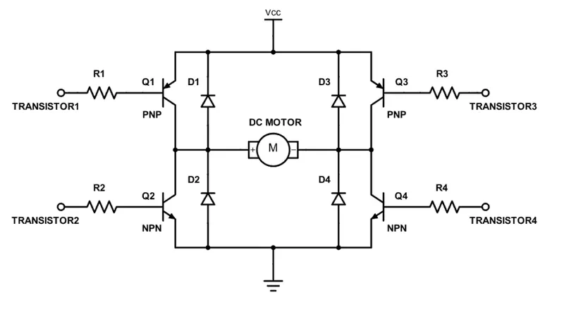
The H-bridge consists of four BJT/Diode pairs (BJT simulated by IGBT models). Two transistors are switched simultaneously: Q1 and Q4 or Q2 and Q3. When Q1 and Q4 are fired, a positive voltage is applied to the motor, and diodes D2-D3 operate as free-wheeling diodes when Q1 and Q4 are switched off. When Q2 and Q3 are fired, a negative voltage is applied to the motor, and diodes D1-D4 operate as free-wheeling diodes when Q2 and Q3 are switched off.
Chopper:
A DC chopper is also known as a DC-DC converter. It is a static device that is used to obtain a variable DC voltage from a constant DC voltage source. A DC-to-DC converter is an electronic circuit or electromechanical device that converts a direct current (DC) source from one voltage level to another. It is a type of electric power converter. Power levels range from very low (small batteries) to very high (high-voltage power transmission). Choppers are of two types- Step Down chopper and Step Up choppers.
Four Quadrant Chopper DC Drive Block:
The 200 HP DC motor is separately excited with a constant 150 V DC field voltage source. The armature voltage is provided by an IGBT converter controlled by two PI regulators. The converter is fed by a 515 V DC bus obtained by rectification of a 380 V AC 50 Hz voltage source. To limit the DC bus voltage during dynamic braking mode, a braking chopper has been added between the diode rectifier and the DC7 block.
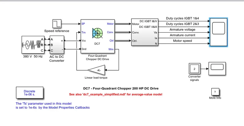
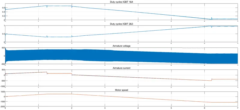
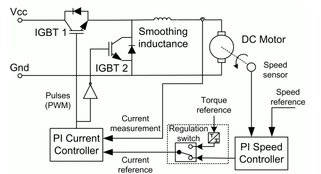
The first regulator is a speed regulator, followed by a current regulator. The speed regulator outputs the armature current reference (in p.u.) used by the current controller to obtain the electromagnetic torque needed to reach the desired speed. The speed reference change rate follows acceleration and deceleration ramps to avoid sudden reference changes that could cause armature over-current and destabilize the system. The current regulator controls the armature current by computing the appropriate duty ratios of the 5 kHz pulses of the four IGBT devices (Pulse Width Modulation). For proper system behavior, the instantaneous pulse values of IGBT devices 1 and 4 are opposite to those of IGBT devices 2 and 3. This generates the average armature voltage needed to obtain the desired armature current. To limit the amplitude of the current oscillations, a smoothing inductance is placed in series with the armature circuit.
Signal Converter:

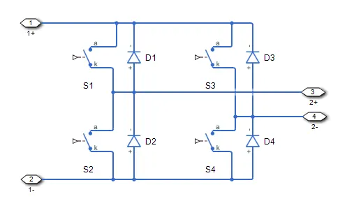
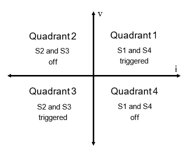
The Four quadrants of operations are Forward Motoring, Forward Braking, Reverse Motoring, and Reverse Braking in the I, II, III, and IV quadrants respectively.
In Quadrant I:
- When S1 is turned ON: When S1 is on, the switches S1 and S4 are triggered, the output voltage (v_o) and output current (i), both are positive and the power flows from the source to load and the inductor stores the energy. The motor rotates in the forward direction and therefore it is called forward motoring.
- When S1 is turned OFF: When S2 is off, the Switch S4 and diode D2 are triggered, output current (i), is positive and the output voltage (v_o) will be zero and the inductor will release energy.
- The Torque and the speed are positive.
In Quadrant II:
- When S2 is turned ON: Assuming the motor is running in the forward direction. Switch S2 and diode D4 are triggered; Output voltage (v_o) becomes zero. The negative output current is attained due to the E and the machine behaves as the generator and the inductor stores energy.
- When S2 is OFF: In this situation, D1 and D4 are triggered and the output current is negative. The inductor releases energy using diodes D4 and D1, the power flows from the load to the source. This is forward braking.
- The Torque is negative and the speed is positive.
In Quadrant III:
- When S3 is ON: The Switches S3 and S2 are triggered and the Output voltage (v_o) and the output current (i) are negative and the power flows from source to load. The inductor stores the energy, the motor rotates in the reverse direction.
- When S3 is OFF: When the switch is off, the S2 and the diode D4 are triggered. The output current is negative and the output voltage is zero. The Polarity of back EMF is reversed.
- The speed and torque are negative.
.In Quadrant IV:
- When S4 is ON: The motor is running in the reverse direction and the switch S4 and diode D2 are triggered output voltage is zero and the machine behaves as a generator and the inductor stores the energy.
- When S4 is OFF: The diode D2 and Diode D3 are triggered. The diodes D2 and D3 are triggered. The output voltage becomes negative and the output current is positive. It is called reverse braking.
- The torque is positive and the speed is negative.
Two Quadrant Chopper DC Drive Block:
The Two-Quadrant Chopper DC Drive (DC6) block represents a two-quadrant, DC-supplied, chopper (or DC-DC PWM converter) drive for DC motors. This drive features closed-loop speed control with a two-quadrant operation. The speed control loop outputs the reference armature current of the machine. Using a PI current controller, the chopper duty cycle corresponding to the commanded armature current is derived. This duty cycle is then compared with a sawtooth carrier signal to obtain the required PWM signals for the chopper.
Compared with other DC drives, the main advantages of this drive are its implementation simplicity and the that it can operate in two quadrants (forward motoring and reverse regeneration). In addition, due to the use of high switching frequency DC-DC converters, a lower armature current ripple (compared with thyristor-based DC drives) is obtained. However, for all two-quadrant DC drives, reversible and regenerative operations (reverse motoring and forward regeneration), which are required in most DC drives, cannot be obtained.
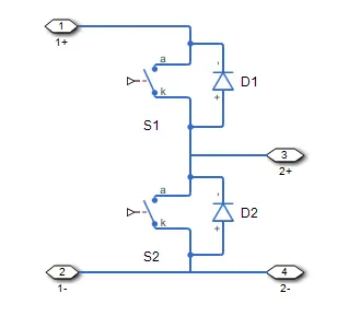
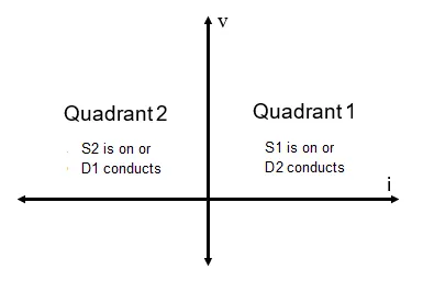
The Two-Quadrant Chopper DC Drive block uses these blocks from the Electric Drives/Fundamental Drive Blocks library:
- Speed Controller (DC)
- Regulation Switch
- Chopper
Procedure:
- Explain and Run MATLAB demo ‘Speed control of a DC motor using BJT-H Bridge’. The armature current shoot-up from the scope results are to be observed.
- Open the MATLAB and In the Help documentation type Speed Control of a DC motor using BJT –H Bridge
- Results tab opens, and then select the model and click Open Model.
- The model is opened in a Simulink workspace.
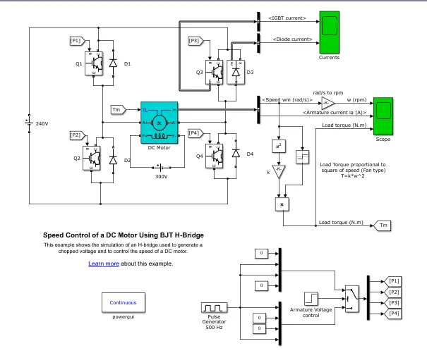
- Run the model as it is and observe the graphs of the armature current.
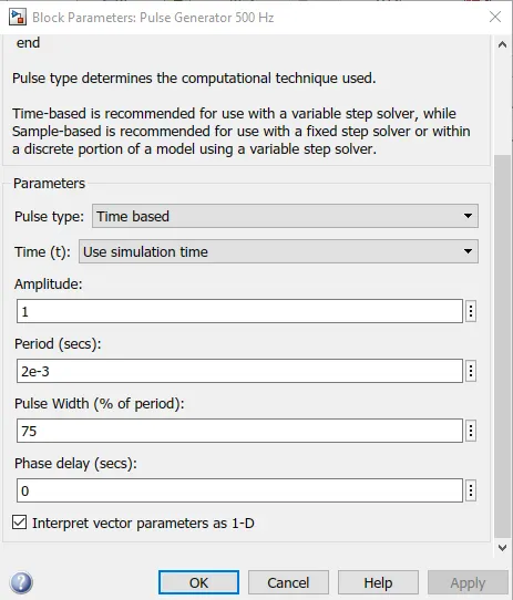
- Now, at the bottom part of the model, there’s a Pulse generator block, click on it and change the Pulse width to 50% and run the model again.
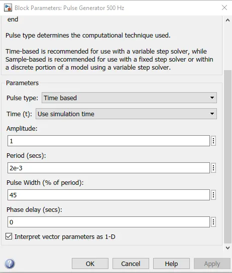
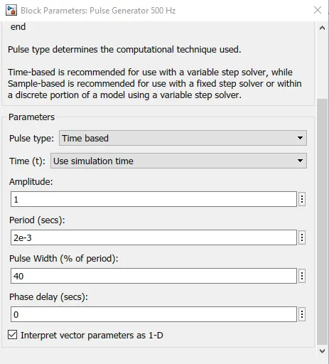
- Check the outputs. Follow the same for 45% and 40% just to check if the armature voltage is decreased sharply after half of the simulation time.
- Refer to the help section of ‘The Four-Quadrant Chopper DC Drive (DC7) block’. Compare it with the H-Bridge model.
- The Stability of the voltage and current supply is higher in the four-quadrant compared to BJT as the four-quadrant uses the step-by-step ramping strategy for the change in the motor direction whereas the stability is lost.
- Regenerative braking is possible in four-quadrant but not in BJT.
- It is widely used in the automobile sector to control DC motor speed and direction in Four-quadrant. Whereas the BJT is used in robotics and electro-mechanical devices to control DC motor speed and direction.
- The current values are continuous in BJT and In Four Quadrants; it is chopped so that the simulation takes less time.
- To change the direction of the motor, current signals are interrupted in four quadrants. Whereas in BJT the polarity of the current needs to be changed.
- The main advantage of the Four-quadrant is that it operates in all four quadrants but BJT can move only in two directions.
- Four Quadrants provides better efficiency and operates at high power levels when compared to BJT that operates at moderate power levels.
- Develop a 2-quadrant chopper using Simulink & explain the working of the same with the relevant results.
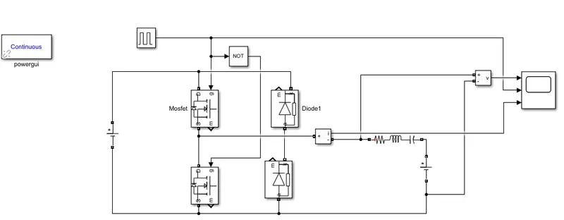
- To create a two-quadrant chopper circuit model, we select the MOSFET which acts as a gate that is connected with a diode.
- The ends of the diode are connected to the current measurement.
- The series RLC branch end is connected to the current measurement and the DC voltage source.
- The Pulse generator is connected to the MOSFET to give a signal to the gate.
- After Connecting a Power GUI is added to show a continuous flow.
- Save the model and run it.
- Observe the plots.
- Explain about BLDC Motor
- A brushless DC electric motor (BLDC motor or BL motor), also known as an electronically commutated motor (ECM or EC motor) or synchronous DC motor, is a synchronous motor using a direct current (DC) electric power supply. It uses an electronic closed-loop controller to switch DC currents to the motor windings producing magnetic fields which effectively rotate in space and which the permanent magnet rotor follows. The controller adjusts the phase and amplitude of the DC pulses to control the speed and torque of the motor. This control system is an alternative to the mechanical commutator (brushes) used in many conventional electric motors.
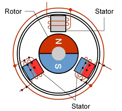
- The construction of a brushless motor system is typically similar to a permanent magnet synchronous motor (PMSM), but can also be a switched reluctance motor, or an induction (asynchronous) motor. They may also use neodymium magnets and be outrunners (the stator is surrounded by the rotor), in runners (the rotor is surrounded by the stator), or axial (the rotor and stator are flat and parallel).
- The advantages of a brushless motor over brushed motors are high power-to-weight ratio, high speed, nearly instantaneous control of speed (rpm) and torque, high efficiency, and low maintenance.
- Brushless motors find applications in such places as computer peripherals (disk drives, printers), hand-held power tools, and vehicles ranging from model aircraft to automobiles.
- In modern washing machines, brushless DC motors have allowed the replacement of rubber belts and gearboxes by a direct-drive design.
- In brushless DC motors, an electronic servo system replaces the mechanical commutator contacts.
- An electronic sensor detects the angle of the rotor and controls semiconductor switches such as transistors which switch current through the windings, either reversing the direction of the current or, in some motors turning it off, at the correct angle so the electromagnets create torque in one direction.
- The elimination of the sliding contact allows brushless motors to have less friction and longer life; their working life is only limited by the lifetime of their bearings.
- Brushed DC motors develop a maximum torque when stationary, linearly decreasing as velocity increases. Some limitations of brushed motors can be overcome by brushless motors; they include higher efficiency and lower susceptibility to mechanical wear.
- These benefits come at the cost of potentially less rugged, more complex, and more expensive control electronics.
- A typical brushless motor has permanent magnets that rotate around a fixed armature, eliminating problems associated with connecting current to the moving armature.
- An electronic controller replaces the commutator assembly of the brushed DC motor, which continually switches the phase to the windings to keep the motor turning.
- The controller performs similar timed power distribution by using a solid-state circuit rather than the commutator system.
- Brushless motors offer several advantages over brushed DC motors, including high torque to weight ratio, increased efficiency producing more torque per watt, increased reliability, reduced noise, longer lifetime by eliminating brush and commutator erosion, elimination of ionizing sparks from the commutator, and an overall reduction of electromagnetic interference (EMI).
- With no windings on the rotor, they are not subjected to centrifugal forces, and because the windings are supported by the housing, they can be cooled by conduction, requiring no airflow inside the motor for cooling. This in turn means that the motor's internals can be entirely enclosed and protected from dirt or other foreign matter.
- Brushless motor commutation can be implemented in software using a microcontroller, or may alternatively be implemented using analog or digital circuits.
- Commutation with electronics instead of brushes allows for greater flexibility and capabilities not available with brushed DC motors, including speed limiting, micro-stepping operation for slow and fine motion control, and a holding torque when stationary.
- Controller software can be customized to the specific motor being used in the application, resulting in greater commutation efficiency.
- The maximum power that can be applied to a brushless motor is limited almost exclusively by heat;[citation needed] too much heat weakens the magnets and will damage the windings' insulation.
- When converting electricity into mechanical power, brushless motors are more efficient than brushed motors primarily due to the absence of brushes, which reduces mechanical energy loss due to friction.
- The enhanced efficiency is greatest in the no-load and low-load regions of the motor's performance curve.
- Environments and requirements in which manufacturers use brushless-type DC motors include maintenance-free operation, high speeds, and operation where sparking is hazardous (i.e. explosive environments) or could affect electronically sensitive equipment.
- The construction of a brushless motor resembles a stepper motor, but the motors have important differences due to differences in implementation and operation.
- While stepper motors are frequently stopped with the rotor in a defined angular position, a brushless motor is usually intended to produce continuous rotation.
- Both motor types may have a rotor position sensor for internal feedback. Both a stepper motor and a well-designed brushless motor can hold finite torque at zero RPM.
Results:
- For the BJT H-Bridge:
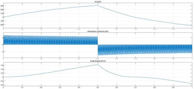
We can observe from the graphs that the decrease in the duty cycle affects the transition time and makes sure that the additional current isn’t passed and therefore showing the sharp drop at half of the duration.
The graph at 75% Duty Cycle:
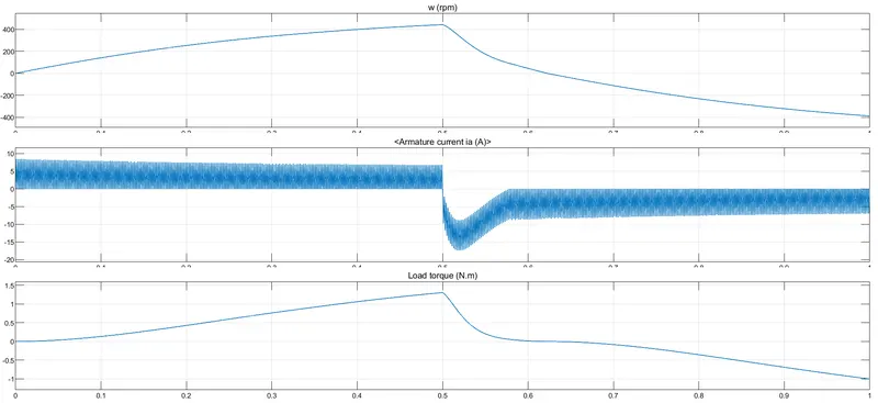
The graph at 45% Duty Cycle:
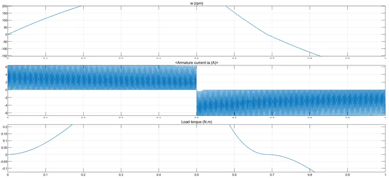
The graph at 40% Duty Cycle:
- For the Two Quadrant Chopper:
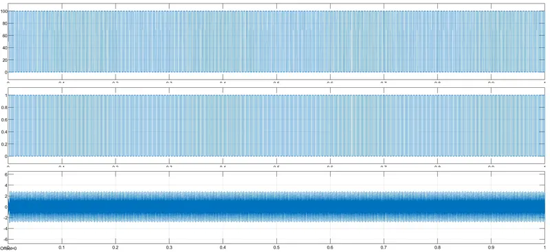
The voltage is positive and the current can be seen as fluctuating source.
Graph:
Learning Outcomes:
- Learned to check the BJT H-bridge and Four-quadrant DC drive.
- Learned to create blocks based on the circuit diagrams.
References: