Study of DC motor control using BJT H-bridge and DC7 block, also operation of BLDC motor
Objective-1:
Run MATLAB demo ‘Speed control of a DC motor using BJT H-bridge’. Modify the model such that the armature current doesn’t shoot up when the motor changes direction from forward to reverse.
Solution:
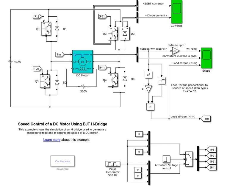
Default input:
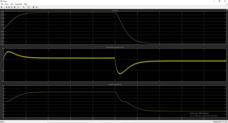
Default output:
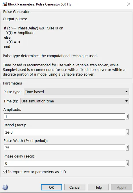
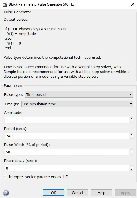
Input parameter:
Output:
Explanation:
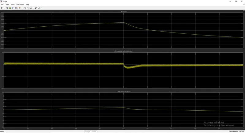
- For armature current doesn’t shoot up when the motor changes direction from forward to reverse we have two methods to do it one by resistance change and another by changing the value of pulse width or duty cycle.
- Here if we change the resistance value there will be more heat generation in the motor which will create losses.
- So here we changed the duty cycle value from 75 to 50 to overcome the shoot when the motor changes its direction from forward to reverse.
- From above if we observe the first plot when the pulse width is 75 we can observe that when the voltage supply is given and 1 and 4 IGBT block are activated in starting there is a transient stage up to some milliseconds after that it achieves the steady-state current up to 0.5 sec with comparison to this behaviour load and torque also behaves the same. As when the voltage supply is been given to 2 and 3 IGBT blocks we can see the armature current changes its direction from positive to negative and the amplitude of the transient stage is also more as compared to 1 & 4 IGBT block and it takes more time as compared to them to come in steady-state and also load and torque starts decreasing gradually when there is a transient state. In this, the maximum speed achieved by the motor is 947 RPM at 6 N-m of load.
- Form overcoming the armature current shoot up I changed the pulse width value to 50 and the plot which we got from that we can observe the transient state has decreased to minimum and there is a steady-state achieved in less time and there are no current losses too. In this, the maximum speed achieved by the motor is 427RPM at 1.3N-m of load.
----------------------------------------------------------------------------------------------------------------------------------------------------------------
Objective-2:
Refer to the help section of ‘The Four-Quadrant Chopper DC Drive (DC7) block’. Compare it with the H-bridge model.
| DC7 Block | H-Bridge model block |
| It is a four-quadrant chopper and can operate in four modes. | It is a two-quadrant and can operate in two modes. |
| The four modes are Forward Motoring, Forward Braking, Reverse Motoring and Reverse Braking. | The two modes are Forward and Reverse. |
| In Four-Quadrant Chopper Regenerative Braking is possible | In H-Bridge regenerative braking is not possible. |
| It is more efficient than the H-Bridge block. | It is less efficient than the DC7 block. |
| In DC7 PI speed controller is used to reduce the speed error or deviation in the circuit | In H-Bridge no speed controller is used. |
| In DC7 current controller is used to control current error or deviations and pass on the required current. | In H-Bridge there is no current controller due to this it's difficult to detect the error in the current output. |
------------------------------------------------------------------------------------------------------------------------------------------------------------------
Objective-3:
Make a suitable EV model using the DC7 block and make a result report.
Default input model:
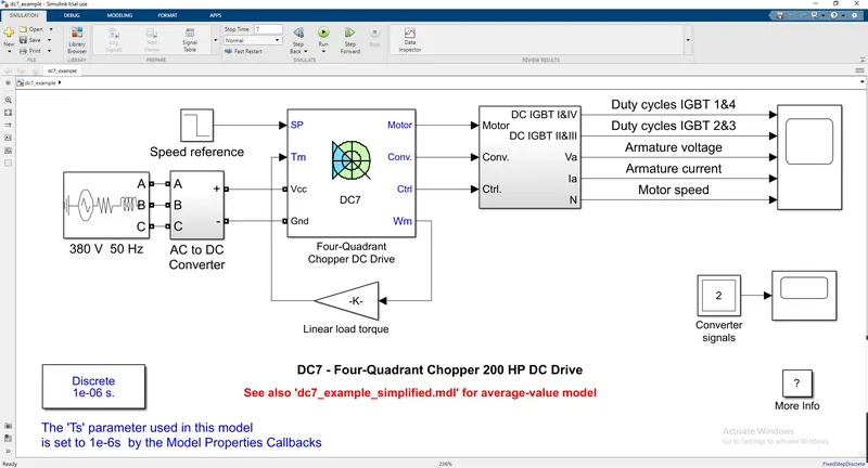
The 200 HP DC motor is separately excited with a constant 150 V DC field voltage source. The armature voltage is provided by an IGBT converter controlled by two PI regulators. The converter is fed by a 515 V DC bus obtained by rectification of a 380 V AC 50 Hz voltage source. In order to limit the DC bus voltage during dynamic braking mode, a braking chopper has been added between the diode rectifier and the DC7 block.
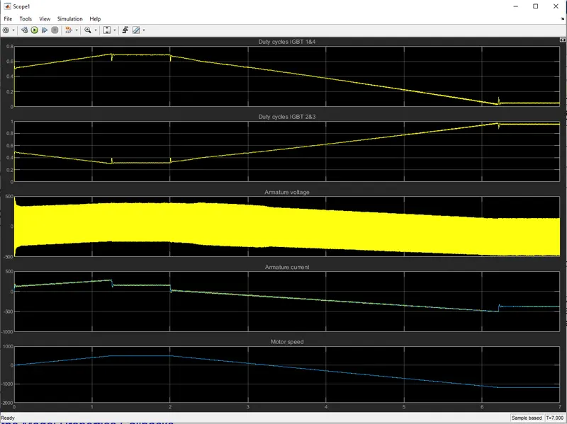
The first regulator is a speed regulator, followed by a current regulator. The speed regulator outputs the armature current reference (in p.u.) used by the current controller in order to obtain the electromagnetic torque needed to reach the desired speed. The speed reference change rate follows acceleration and deceleration ramps in order to avoid sudden reference changes that could cause armature over-current and destabilize the system. The current regulator controls the armature current by computing the appropriate duty ratios of the 5 kHz pulses of the four IGBT devices (Pulse Width Modulation). For proper system behaviour, the instantaneous pulse values of IGBT devices 1 and 4 are opposite to those of IGBT devices 2 and 3. This generates the average armature voltage needed to obtain the desired armature current. In order to limit the amplitude of the current oscillations, a smoothing inductance is placed in series with the armature circuit.
Default Output:
Input:
Input spreadsheet link:https://docs.google.com/spreadsheets/d/1YAi9wiEHeUFySeOFil1CLWCWWv-yVfJ_IpvYoIZPxJI/edit?usp=sharing
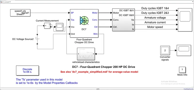
- We changed the default model blocks for getting EV model output.
- First, we changed the AC power supply source to DC supply with 100 v constant value, we also used the current measurement block to measure the current input which we fed to the model.
- Instead of linear load torque block, we gave subsystem block.
- In subsystem we implemented torque equation using blocks, `T=24.7+0.0051*omega^2`, we used two constant blocks for constant values and square block to square the speed value which is the input we used input block for it and add a block to add the equation and finally the output block which is connected o the torque port in four-quadrant Dc- wave block.
- Instead of speed reference, we gave the drive cycle made in an excel file and gave it as the input using from spreadsheet block.
Output:
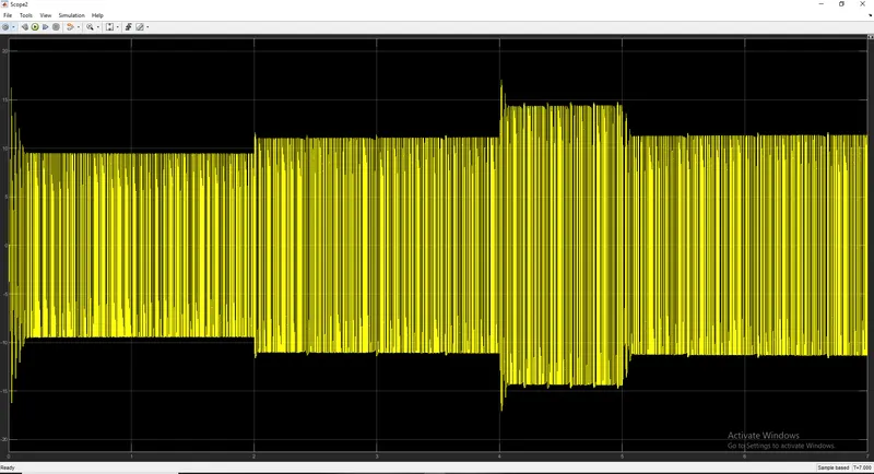
Output of Current measurement:
Result:
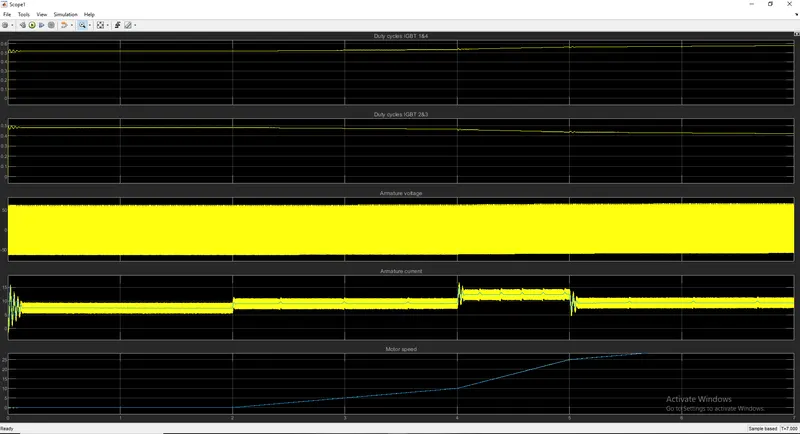
- As we observe by the plot as the armature voltage is from 50 to -50 this is because the input dc voltage is 100 v and here 4 IGBT are used so the voltage is calculated in forward and reverse directions.
- Armature current is in the transient state in starting of the voltage supply compared to motor speed we can observe that there are some deviations in speed as well. After some milliseconds the current is constant till 0.5 sec again it is in the transient state as there is an increase in the speed as the duty cycle is also increased.
- Here we can observe reference and actual armature current and motor speed are almost the same.
- Here the motor speed is 0 up to 2 sec after that it starts increasing as per the drive cycle input data.
- The Peak motor speed which we are getting here is 35 Rad/sec.
- As we observe armature current and speed there is a co-relation between them as speed increases there is some deviation in current supply and a speed is constant current supply is also constant.
------------------------------------------------------------------------------------------------------------------------------------------------------------------
Objective-4:
Explain in a brief the operation of the BLDC motor
Introduction of BLDC:
A brushless DC motor (known as BLDC) is a permanent magnet synchronous electric motor which is driven by direct current (DC) electricity and it accomplishes an electronically controlled commutation system (commutation is the process of producing rotational torque in the motor by changing phase currents through it at appropriate times) instead of a mechanical commutation system. BLDC motors are also referred to as trapezoidal permanent magnet motors. The efficiency of BLDC motors is typically 85 to 90 per cent, whereas brushed type DC motors are 75 to 80 per cent efficient. There are wide varieties of BLDC motors available ranging from small power range to fractional horsepower, integral horsepower and large power ranges.
Diagram:
Construction:
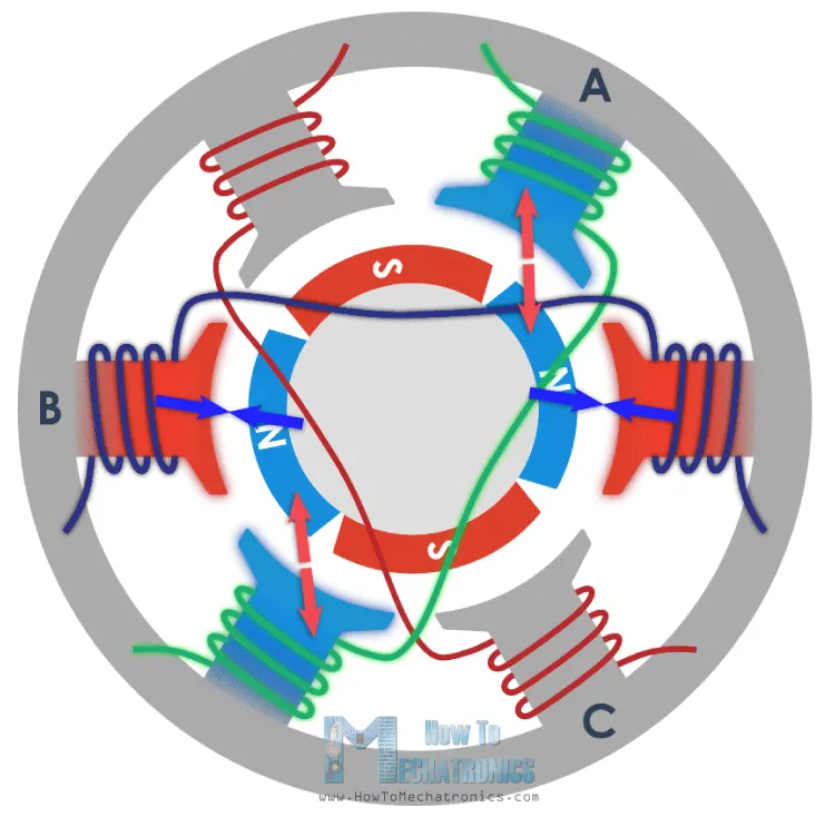
BLDC motors can be constructed in different physical configurations. Depending on the stator windings, these can be configured as single-phase, two-phase, or three-phase motors. However, three-phase BLDC motors with permanent magnet rotor are most commonly used.
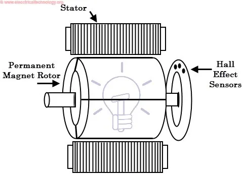
Stator: The stator of a BLDC motor made up of stacked steel laminations to carry the windings. These windings are placed in slots that are axially cut along the inner periphery of the stator. These windings can be arranged in either star or delta. However, most BLDC motors have three-phase star connected stator.
Rotor: BLDC motor incorporates a permanent magnet in the rotor. The number of poles in the rotor can vary from 2 to 8 pole pairs with alternate south and north poles depending on the application requirement. In order to achieve maximum torque in the motor, the flux density of the material should be high.
Hall sensor: Hall sensor provides the information to synchronize stator armature excitation with rotor position. Since the commutation of the BLDC motor is controlled electronically, the stator windings should be energized in sequence in order to rotate the motor. Before energizing a particular stator winding, acknowledgement of rotor position is necessary. So the Hall Effect sensor embedded in the stator senses the rotor position.
Working principle:
BLDC motor works on a principle similar to that of a conventional DC motor, i.e., the Lorentz force law which states that whenever a current-carrying conductor placed in a magnetic field it experiences a force. As a consequence of reaction force, the magnet will experience an equal and opposite force.
Working:
In the case of, BLDC motor, the current-carrying conductor is stationary while the permanent magnet moves. When the stator coils are electrically switched by a supply source, it becomes an electromagnet and starts producing the uniform field in the air gap. Though the source of supply is DC, switching makes to generate an AC voltage waveform with a trapezoidal shape. Due to the force of interaction between the electromagnet stator and permanent magnet rotor, the rotor continues to rotate.
Advantages:
- It has no mechanical commutator and associated problems
- High efficiency due to the use of permanent magnet rotor
- High speed of operation even in loaded and unloaded conditions due to the absence of brushes that limits the speed
- Smaller motor geometry and lighter in weight than both brushed type DC and induction AC motors
- Long-life as no maintenance is required for commutator system
Disadvantages:
- These motors are costly
- The electronic controller required to control this motor is expensive
- Not much availability of many integrated electronic control solutions, especially for tiny BLDC motors
- Requires complex drive circuitry
- Need of additional sensors
Applications:
- Computer hard drives and DVD/CD players
- Electric vehicles, hybrid vehicles, and electric bicycles
- Industrial robots, CNC machine tools, and simple belt-driven systems
- Washing machines, compressors and dryers
- Fans, pumps and blowers
------------------------------------------------------------------------------------------------------------------------------------------------------------------
Conclusion:
- Model modified so that motor doesn't shoot up while changing from forward to reverse.
- Distuinshed between H-Bridge and DC7 block.
- Ev model made using DC7 block.
- Explained in the brief working of BLDC motor.