Week-7 Challenge: DC Motor Control
Answer 1: The BJT-H bridge model for speed controlling of DC motor uses BJT for power switching applications. The transistor used is of IGBT type(Insulated Gate Bipolat Transistor). When it is conducting (BjT operating in the saturated region), a forward voltage Vf is developed between collector and emitter in the range of 1 V. Therefore, the IGBT block can be used to model the BJT device. The switch is controlled by simulink signal. The signal is generated at the pulse generator. The armature mean voltage can be varied from 0 to 240 V when the duty cycle is varied from 0 to 100%. This duty cycle is specified at the pulse generator. For example, for 75% duty cycle the pulse width for % of period is 75 which sets the IGBT on for 75% and thus average voltage would be 0.75*240 volts = 180 volts.
This is the results of diode working as free-wheeling for the rest 25% of time when the switches are off. Similarly, for 50% duty cycle, set the pulse width to 50% of the cycle period and 0.5*240 volts = 120 volts will be the average voltage supplied to the motor.
We now understand the working of the model. Now lets understand the current shootup reason and how to reduce it.
The armature current for the set 75% duty cycle shoots up at starting as well as when the direction of current is reversed.
Why this happens during starting: the voltage is the sum of back emf generated and the product of current and resistance. As the rotor is at rest during starting there is no back emf generated and so the voltage is equal to product of current and resistance. As the emf is zero and the resistance is same throughout the current is the only parameter that varries hence it is high at zero back emf. But as the speed of the rotor increases the back emf starts to increase and current dereases and reach a stable value.
Why current shoots up during direction change: when the current direction is changed the voltage equation for this is also same as back emf plus the current and resistance product. Also the rotor rotation should also be reversed in order for equation to work. The rotor does not reverse its direction as soon as the current is reversed but takes time to first come to zero and then start to rotate in reverse direction. So for this period when the current is reverse and the rotor rotates in opposite to the nature of current till it reaches zero the back emf is also reverse and adds up in the current value in the reverse direction. When the rotor reaches zero speed and starts rotating in the desired direction of the current it work. Similar to the starting voltage equation, the back emf being zero at start. hence this surge in current is also taken into account. So compared to the starting armature current, the shootup in the direction change is more.
We can see from the scope that the current shootup when direction changed is more than the starting shootup
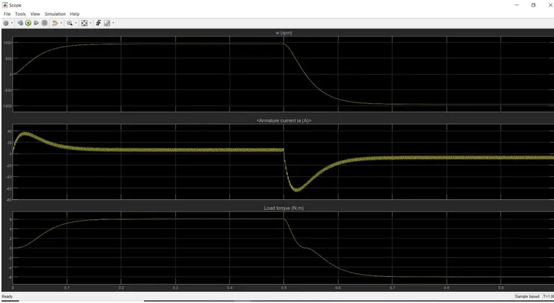
What role does duty cycle play: Simply, when we set duty cycle to 75%, it means the on state of the switch would be 75% of the cycle and it will be off for the remaining 25% of the cycle time. Now, during on state the current surge slope is less and for off period the slope is more. Or in short we can say during on time the current takes more time to reach the peak and when off the current drops ata faster rate. And hence due to this tendency of the motor to drop current at faster rate than to rise leads to higher shootup during switching and takes more span to come to normal stable state of the armature current.
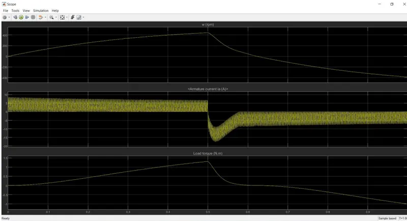
When the duty cycle is at 50% we similarly have the same probelm that rise in the current takes more time but dripping down is a lot faster. So as the shootup during starting is above the stable level, it can be dropped comparitively faster then the shootup at the change in current direction. Because the change in direction has the shootup in negative direction and we know that the tendency of the current is to drop faster than to rise. At 50% duty cycle we are able to drive away the starting shootup at the start but still the shootup during current change is present. It can be seen in the graph below.
Reducing the duty cycle reduces the on time of the switch and increases the off time. So, during off state the current slope is higher, hence reducing helps to drive away the shootup current. The graph below shows the armature current, load torque and speed in rpm at 44% duty cycle.
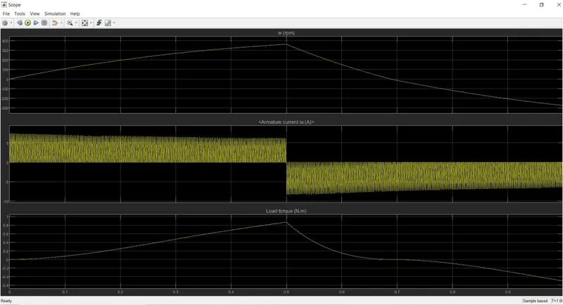
As the duty cycle reduces the average voltage across the system also reduces. For 44% duty cycle the volatge is 105.6 voltage. Hence, the speed and load torque also reduces as the voltage and the duty cycle reduces.
In this way we have successfully modelled the BJT H bridge so that the armature current doesn’t shootup during change in current direction.
Answer 2: The comparison between the two models is listed in the following points.
⦁ Both the models are choppers for a dc voltage to average the value as per the duty cycle.
⦁ The duty cycle in the BJT is fixed and specified for a particular simulation and you can change it for the next simulation directly.
⦁ The duty cycle in the DC7 model is governed from the current controller from the current requirement data which is the output from reference speed.
⦁ It means the DC7 model works with respect to the requirement or the reference for the simulation.
⦁ The bjt does not account any duty cycle variation in order to achieve any speed change. For both forward and reverse motoring the duty cycle remains same for the BJT model.
⦁ As mentioned, the duty cycle changes in DC7 model according to the reference speed and in both forward and reverse motoring.
⦁ The dtuy cycle controlling part is governed by the same instruments in both the models. That is the use of IGBT and Diode. The IGBTs remain on and off with respect to the duty cycle to bring up a mean or averaged voltage in the system which is carried by diodes when the switches are off.
⦁ The working of lGBTs and Diodes is same in both except the governing of these IGBTs is different.
⦁ The simulation time taken is alot more in the DC7 as it uses microseconds time step for solving. The bjt uses a variable step timer and a solver to solve, hence simulates the model very fast.
Answer 3:
Introduction: A DC7 block is an four quadrant chopper that is used in DC drives during speed regulation. The example consists of a200HP DC motor and a 380V 50Hz AC supply. This alternating current is then converted to direct current by a rectifier and fed to the DC motor as per the required speed. The current required is monitered from the speed reference provided to the model and the thus the required current for that speed is fed with the help of chopper. The chopper works by the aid of lGBTs and diodes and work according to the duty cycles.
Objective: To convert the above model to an EV model.
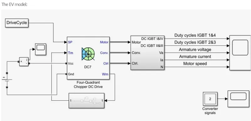
Solution: To covert the DC7 example model to an EV model we follow the following changes.
⦁ As we have a specific speed reference in the example model, we have to replace it with the speed of a vehicle which we daily observe. This can be done by adding the drive cycle values to the workspace and then apply it to the model with the help of a block called 'from workspace'
⦁ Now, the load applied to the motor was a small fan load which had a linear load torque. In our case the load torque is different and it changes with respect to the speed changed. So, we have a torque speed equation T=24.7+0.0051w^2 which includes vehicle load, aerodynamic load and motor charecteristics. Hence replace the linear load torque with the above torque equation.
⦁ The supply to an EV will be a DC stored in a battery, but in the example it is opposite, so we replace it with a DC voltage source and connect to the dc block.
⦁ Change the stop time to the time that is given as the speed input.
The DC7 Example:
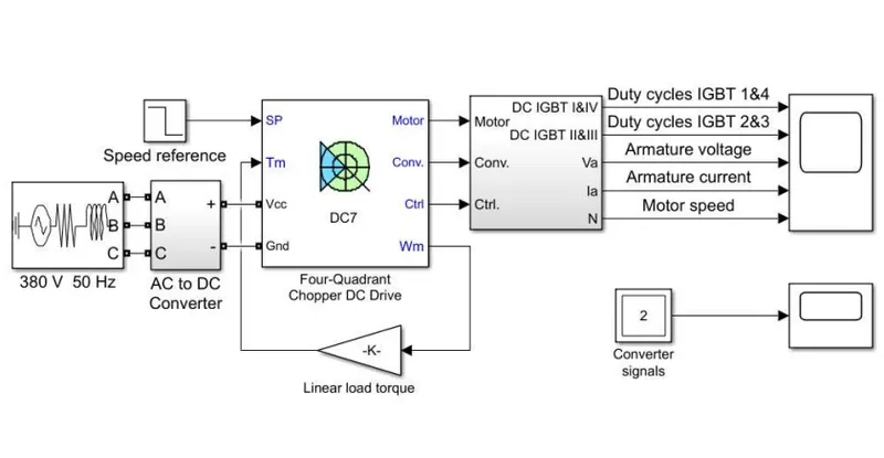
Now running the simulation we get following results.
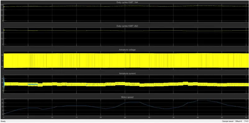
Result: The above plot shows the simulation result of an EV drive cycle. The speed input data is accurately observed in the motor speed graph. The variation in speed with acceleration, decceleration and constant speed etc, is properly achieved. The armature current is also seen to increase and decrease with respect to increase and decrease in speed. However, at constant speed, due to the back emf and the switching tendencies of the IGBTs the current is seen fluctuating. The magnitude of the voltage is seen in both positive and negative side which is nothing but the change in direction of polarity when switches are off. The IGBTs also show opposite nature of magnitude.