Week-7 Challenge: DC Motor Control
AIM:
- Run a MATLAB demo 'Speed Control of a D.C Motor using BJT H-Bridge' modify the model such that armature current doesn't shoot up when motor changes direction from forward to reverse.
- Refer to help section of the 'Four Quadrant Chopper D.C Drive (DC7) Block' compare it with H-Bridge model.
- Make a suitable model using DC7 Block and make result report.
- To explain in a brief about operation of BLDC motor.
STUDY-1:
Bipolar Junction Transistor:
A Bipolar Junction Transistor (also known as a BJT or BJT Transistor) is a three-terminal semiconductor device consisting of two p-n junctions which are able to amplify or magnify a signal. It is a current controlled device. The three terminals of the BJT are the base, the collector and the emitter. A BJT is a type of transistor that uses both electrons and holes as charge carriers.A signal of small amplitude if applied to the base is available in the amplified form at the collector of the transistor. This is the amplification provided by the BJT. Note that it does require an external source of DC power supply to carry out the amplification process.
There are two types of bipolar junction transistors – NPN transistors and PNP transistors. A diagram of these two types of bipolar junction transistors is given below.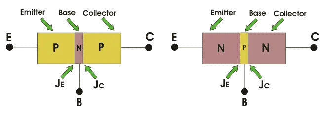
From the above figure, we can see that every BJT has three parts named emitter, base and collector. JE and JC represent the junction of emitter and junction of collector respectively. Now initially it is sufficient for us to know that emitter based junction is forward biased and collector-base junctions are reverse biased. The next topic will describe the two types of these transistors.
H-bridge:
- An H-bridge is a simple circuit that lets you control a DC motor to go backward or forward.
- You normally use it with a microcontroller, such as an Arduino, to control motors.
- When you can control two motors to go either forward or backward – you can build yourself a robot!
H-BRIDGE CONCEPT:
Here’s the concept of the H-bridge:
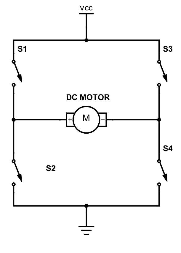
A DC motor spins either backward or forward, depending on how you connect the plus and the minus.
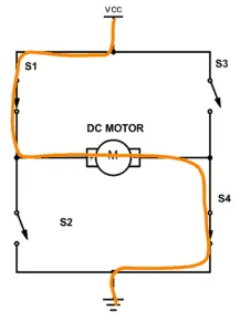
If you close switch 1 and 4, you have plus connected to the left side of the motor and minus to the other side. And the motor will start spinning in one direction.
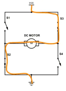
If you instead close switch 2 and 3, you have plus connected to the right side and minus to the left side. And the motor spins in the opposite direction.
THE H-BRIDGE CIRCUIT:
You can build an H-bridge with four transistors.
If you’re not sure how the transistor works, I recommend you read the article How Transistors Work first. From there you’ll learn that the transistor can work as a switch that you can open and close with the voltage on the base.
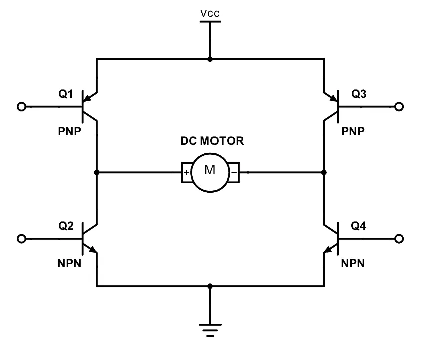
Since the transistor can be a switch, you’ll be able to make the motor spin in either direction by turning on and off the four transistors in the circuit above.
The Bipolar Junction Transistor (BJT) when used for power switching applications, operates as an IGBT. When it is conducting (BJT operating in the saturated region), a forward voltage Vf is developed between collector and emitter (in the range of 1 V). Therefore, the IGBT block can be used to model the BJT device.
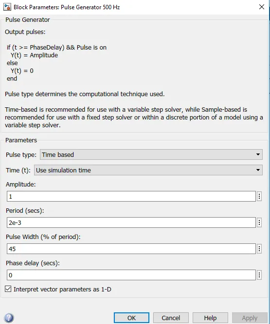
The IGBT block does not simulate the gate current controlling the BJT or IGBT. The switch is controlled by a Simulink® signal (1/0). The DC motor uses the preset model (5 HP 24V 1750 rpm). It simulates a fan type load (where Load torque is proportional to square of speed). The armature mean voltage can be varied from 0 to 240 V when the duty cycle (specified in the Pulse Generator block) is varied from 0 to 100%.
The H-bridge consists of four BJT/Diode pairs (BJT simulated by IGBT models). Two transistors are switched simultaneously: Q1 and Q4 or Q2 and Q3. When Q1 and Q4 are fired, a positive voltage is applied to the motor and diodes D2-D3 operate as free-wheeling diodes when Q1 and Q4 are switched off. When Q2 and Q3 are fired, a negative voltage is applied to the motor and diodes D1-D4 operate as free-wheeling diodes when Q2 and Q3 are switched off.
MAIN MODEL:
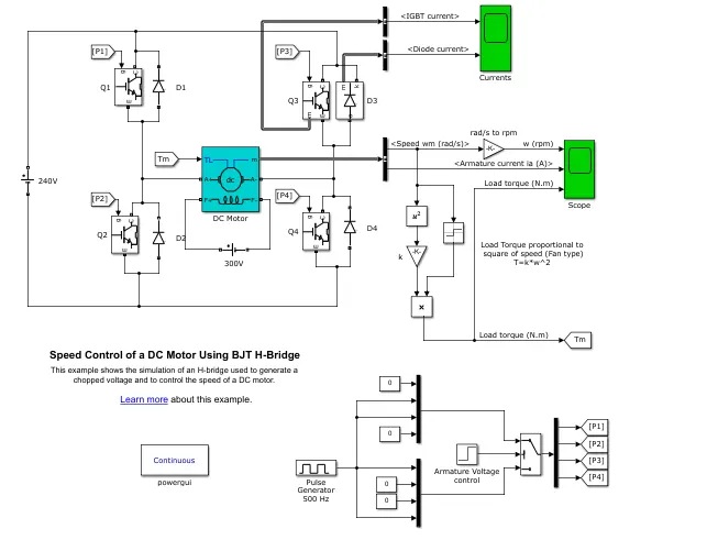
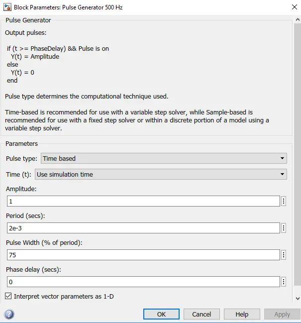
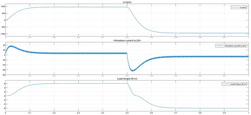
The motor starts in the positive direction with a duty cycle of 75% (mean DC voltage of 180V). At t= 0.5 sec., the armature voltage is suddenly reversed and the motor runs in the negative direction.
'Scope' shows motor speed, armature current and load torque and 'Currents' shows currents flowing in BJT Q3 and diode D3.
RESULT:
75% duty cycle:
we have changed the duty cycle of the battery and observed the variation in armature current, pulse width reduces to 45%.
RESULTS:
45% Duty Cycle:
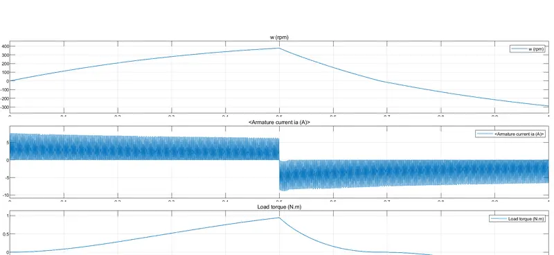
Armature current drops by reducing the duty cycle level.
STUDY-2:
Four Quadrant Operation of Motors:
We know that,
(1) All types of DC-DC converters are capable of operating the motor operation in the first quadrant.
(2) Some converters are capable of operating in two quadrants and some in all four quadrants.
(3) Power semiconductor devices(like SCR, MOSFET) used in chopper circuits are unidirectional devices.
(4) So the polarities of output voltage VO and the direction of output current IO are restricted.
(5) However, by using appropriate arrangement of semiconductor devices and passive components, a chopper can operate in any of the four quadrants.
Based on the number of quadrant a chopper can operate, the chopper circuits can be classified as follows:
- Single Quadrant Chopper:-
Example: Type-A Chopper, Type-B Chopper - Two quadrant Chopper:-
Example: Type-C Chopper, Type-D Chopper - Four quadrant Chopper;-
Example: Type-E Chopper
In some text books these chopper circuits are mentioned as Class-A, Class-B …. Class-E in place of Type-A, Type-B….. Type-E respectively.
In this Post, we will discuss about the four quadrant operation in detail.
Before proceeding further it is highly recommended to know about the basics, principle of operation, classification of DC-DC Converter Circuits (Choppers).
Four Quadrant Operation of Motor:
- When a motor draws power from supply, the voltage and current are in the same direction.
- Now the motor is said to be in motoring operation, its operation corresponds to first quadrant.
- If there is a possibility of reversing the current direction keeping the voltage polarity same, the motor is said to be operating in second quadrant.
- This happens when regenerative braking is applied on the motor.
- During regeneration operation, reverse power flow will happen. ie, power will fed back to the supply system.
- If the voltage polarity and load current are reversed simultaneously, the motor’s operation will be in the opposite direction ( but the power is consumed by the load).
- This operation is corresponds to the third quadrant and even now it is said to be in motoring operation (in reverse direction).
- If the voltage polarity is reversed maintaining the current direction from source to load, the power reversed and the operation corresponding to the fourth quadrant.
- Now the motor is said to be in reverse regeneration operation (ie, regeneration in reverse direction).
Comparing the model of Four Quadrant chopper DC drive with H-Bridge:
DC Four Quadrant Chopper:
- The armature voltage is provided by IGBT controllers is controlled by PI regulations.
- A braking chopper has been added between the diode and motor.
- This model contains speed and current regulators.
- The speed regulation represents armature current used by the current controller in order to obtain the electromagnetic torque needed to reach the desired speed.
- The chopper converts the fixed DC voltage to variable DC voltage.
- It requires current for each sector and consists of four quadrant motoring,forward motoring,forward regenrative braking, reverse motoring and regenrative reverse braking.
- Current signal is interrupted with one other to change the direction of the motor.
- The change in direction in BJT is done by changing the polarity.
- PID controller is used in DC7 model.
H-Bridge model:
- It consists of two operations forward motoring and reverse motoring.
- It is used in robotics technology.
- PID controllers are not used in this model.
- It operates in 2 quadrants.
- In this model the currents changes as there is a change in the polarity in switches.
- This model is discrete.
- Speed controller and current controller sampling times are present.
- The current shoot up and disturbances are high in this due to switching.
STUDY-3:
To build an EV model using DC7 motor:
MAIN MODEL:
DC7- Four-Quadrant Chopper 200 HP DC Drive:
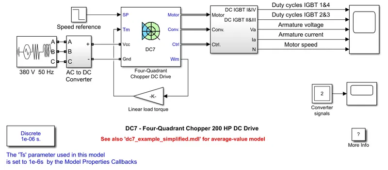
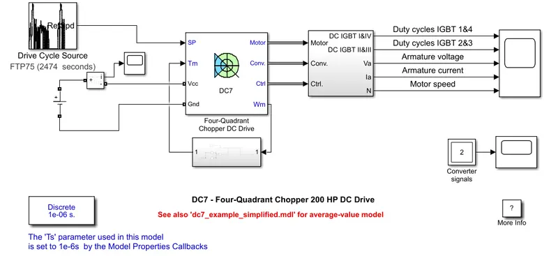
- To build an EV model we use DC7 four quadrant motor.
- Open the DC7 four quadrant copper 200 HP DC drive.
- Remove blocks of electrical source , speed reference and torque inputs.
- The sources are given by voltage sources and for current measurememt, we use current measurement block. and also connect the scope to view the current value.
- Use default drive cycle (FTP75) and fiven as input.
- Create a subsystem for defined equation i.e, `T = 24.7+0.0051 omega^2`
- Create blocks for this relation and join with DC motor.
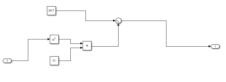
EV model:
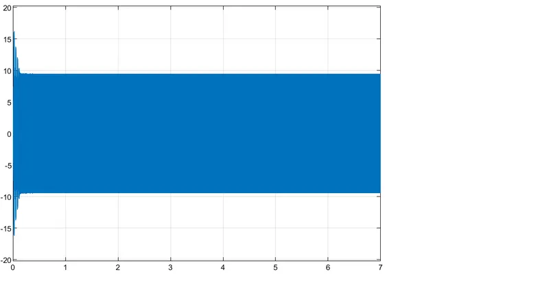
Input Current Supply Scope:
RESULT:
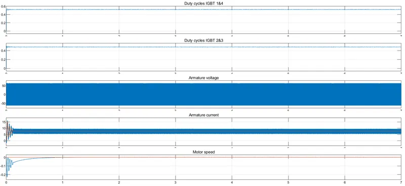
- We can observe the results obtained for model simulation.
- Duty cycle for four IGBTs areshown.
- The armature current and motor speed arevaried intially and voltage is maintaned same.
STUDY-4:
BRUSHLESS DC MOTOR:
A brushless DC motor (also known as a BLDC motor or BL motor) is an electronically commuted DC motor which does not have brushes. The controller provides pulses of current to the motor windings which control the speed and torque of the synchronous motor.
These types of motors are highly efficient in producing a large amount of torque over a vast speed range. In brushless motors, permanent magnets rotate around a fixed armature and overcome the problem of connecting current to the armature. Commutation with electronics has a large scope of capabilities and flexibility. They are known for smooth operation and holding torque when stationary.
Before explaining the working of a brushless DC motor, it is better to understand the function of a brushed motor. In brushes motors, there are permanent magnets on the outside and a spinning armature which contains electromagnet is inside. These electromagnets create a magnetic field in the armature when the power is switched on and help to rotate the armature.The brushes change the polarity of the pole to keep the rotation on of the armature. The basic working principle for the brushed DC motor and for brushless DC motor are same i.e. internal shaft position feedback.
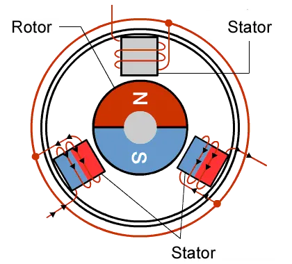
Brushless DC motor has only two basic parts: rotor and the stator. The rotor is the rotating part and has rotor magnets whereas stator is the stationary part and contains stator windings. In BLDC permanent magnets are attached in the rotor and move the electromagnets to the stator. The high power transistors are used to activate electromagnets for the shaft turns. The controller performs power distribution by using a solid-state circuit.
The advantages of a BLDC motor are:
- Brushless motors are more efficient as its velocity is determined by the frequency at which current is supplied, not the voltage\.
- As brushes are absent, the mechanical energy loss due to friction is less which enhanced efficiency.
- BLDC motor can operate at high-speed under any condition.
- There is no sparking and much less noise during operation.
- More electromagnets could be used on the stator for more precise control.
- BLDC motors accelerate and decelerate easily as they are having low rotor inertia.
- It is high performance motor that provides large torque per cubic inch over a vast sped rang.
- BLDC motors do not have brushes which make it more reliable, high life expectancies, and maintenance free operation.
- There is no ionizing sparks from the commutator, and electromagnetic interference is also get reduced.
- Such motors cooled by conduction and no air flow are required for inside cooling.
The disadvantages of a BLDC motor are:
- BLDC motor cost more than a brushed DC motor.
- The limited high power could be supplied to BLDC motor, otherwise, too much heat weakens the magnets and the insulation of winding may get damaged.
CONCLUSION:
- Running 'Speed Control of a D.C Motor using BJT H-Bridge' modify the model such that armature current doesn't shoot up when motor changes direction from forward to reverse.
- Studying on the 'Four Quadrant Chopper D.C Drive (DC7) Block' compare it with H-Bridge model.
- Building a suitable model using DC7 Block and make result report.
- To brief about operation of BLDC motor.