Week-7 Challenge: DC Motor Control
1)Speed control of a DC motor using BJT H-bridge
AIM
To run a MATLAB demo ‘Speed control of a DC motor using BJT H-bridge’ and then modify the model such that armature current doesn’t shoot up when motor changes direction from forward to reverse.
PROCEDURE
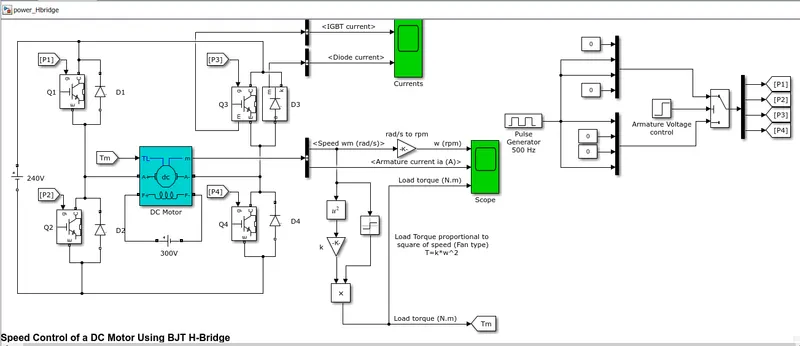
This is the block diagram of the MATLAB demo ‘Speed control of a DC motor using BJT H-bridge’.
Run this simulink model and then open the scope.
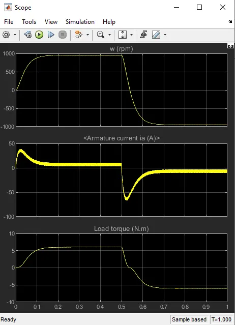
Here we can see that the armature current suddenly rises to a high value when the direction of the motor is reversed.
The reason for this shoot up in current value is , when the direction of rotation is changed , the already induced voltage which opposed the forward rotation will now be in the same direction when the rotation is reversed at the initial stage. So this will increase the current as the resistance is less at the beginning of this reversed rotation.
Similarly we can see the current shooting up when motor is turned ON. This happens because during the start of a motor there is no resistance inside and so the current required to the start the motor will be very high. And the back emf will be zero at the start.
Now to avoid the shoot up we can reduce the input current so that the shoot up is not that high or not visible in the graph. To do so we need to change the duty cycle of the motor.
In the default condition , duty cycle value is 75% (180V).
Now reduce this duty cycle value till the hike in armature current is not visible.
To change this duty cycle , open the pulse generator block as shown below,
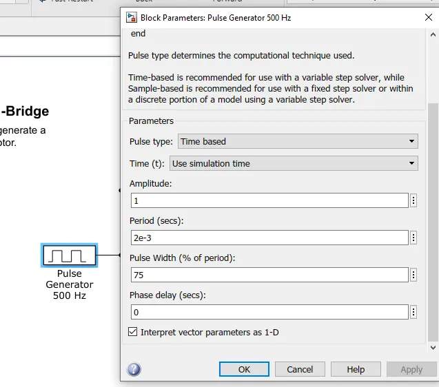
Then change the phase value.
In this case at 45% phase value the armature current doesn’t shoot up as seen earlier.
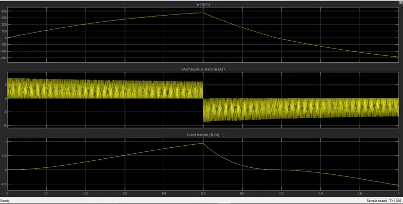
In this result we can see that the armature current doesn’t shoot up like it did in the case of 75% duty cycle.
CONCLUSION
The MATLAB demo ‘Speed control of a DC motor using BJT H-bridge’ has been run successfully and also modified the model in such a way that the armature current doesn’t shoot up when motor changes direction from forward to reverse.
2) Refer to help section of ‘The Four-Quadrant Chopper DC Drive (DC7) block’. Compare it with H-bridge model.
A four quadrant chopper DC drive is a DC to DC Pulse Width Modulation converter that works with DC supply. This type of drive features closed loop control with four quadrant operation. This is done using a PI controller. This is one of the major advantage of this drive compared to others. It can operate in all four quadrants , that is, forward motoring, reverse regeneration, reverse motoring, and forward regeneration. One of the drawbacks of this drive is that it requires four switching devices which will increase the complexity of the drive system.
Comparing H-bridge model with four quadrant DC drive , we can see that the H-bridge dive cannot be used to control the motor output to the extend which a four quadrant can. Also the H-bridge does not operate in all four quadrants. But when it comes to the design and manufacturing , H-bridge type is simple and less complex compared to four quadrant chopper drive.
3) Make a suitable EV model using DC7 block and make result report.
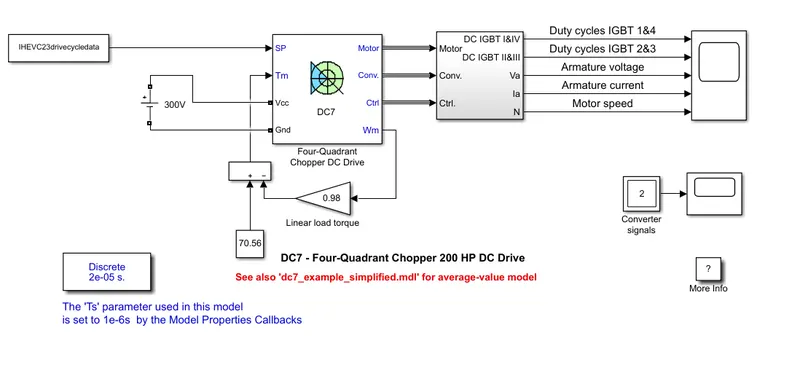
For this purpose we have used the MATLAB example model of four quadrant chopper 200HP DC drive motor and modified it.
The torque input has been changed to the following equation,
`T=70.56-omega_m/1.02`
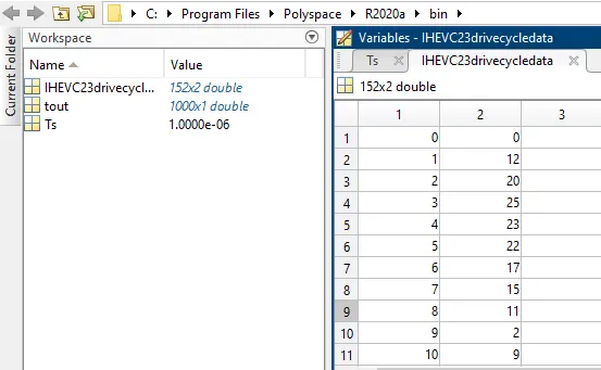
The drive cycle data is also modified as follows,
Input voltage has been changed to 300V DC source.
The modified block diagram is shown below,
The simulation is run for 10 seconds.
The output of this simulation is as follows,
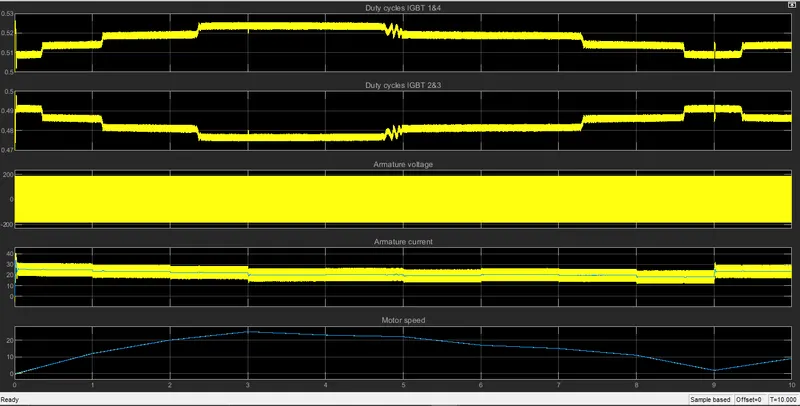
Here we can see that the duty cycle increases sharply at the beginning. This increase in duty cycle is necessary to start the motor form the state of rest.
Then as the motor speed increases as per the drive cycle, the duty cycle for IGBT 1&4 starts to increase. This rise in duty cycle continue till the motor speed reaches the maximum. And when the deceleration of the motor starts the duty cycle also starts to decrease correspondingly. And another thing to notice is that when the motor speed is zero at the 9th second , we can see the spike in duty cycle as seen during the start of this drive cycle.
The armature current of the motor is very high at the beginning till 3 seconds after which it maintains almost a constant pattern throughout the range till 9 seconds.
Now coming to the duty cycles of IGBT 2&3 we can see that this graph is an exact mirror image of the duty cycles of IGBT 1&4. Here we can see that the duty cycles increases when the motor speed decreases. That is in this case regeneration is taking place. And in this case maximum duty cycle value is below 0.5 whereas in case of IGBT 1&4 it is above 0.5.