Week-7 Challenge: DC Motor Control
- Run MATLAB demo ‘Speed control of a DC motor using BJT H-bridge’. Modify the model such that armature current doesn’t shoot up when motor changes direction from forward to reverse.
SOLUTION:- The H-bridge is a simple network where the current flows in both the direction through the motor when the switch is turned ON and OFF.
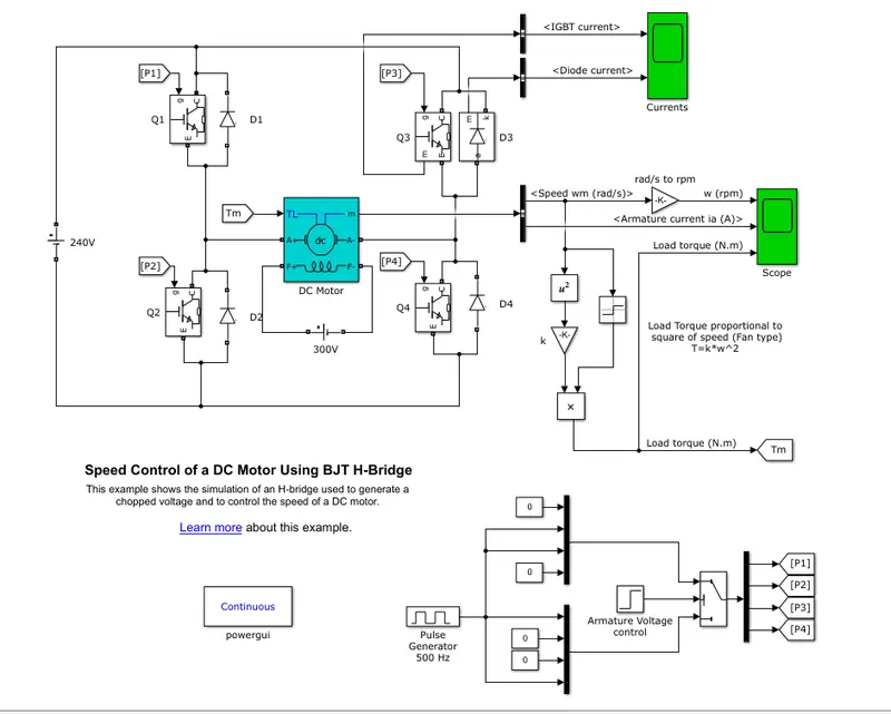
Here in this we will be using 4 BJT.
When Q2 and Q3 are kept closed and Q1 and Q4 are operating the motor rotates and we get a positive rotation of the motor shaft in the above graph and if we do vice versa we will get a negative rpm of the shaft in the graph.
Below is the image of IGBT and DIODE current
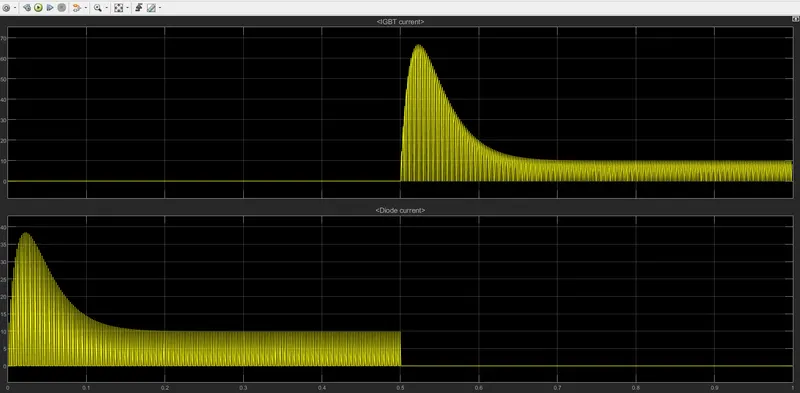
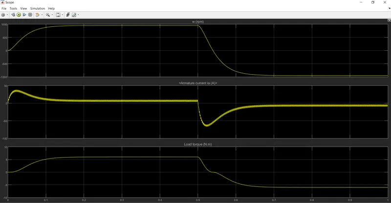
The above graph is for a 75% duty cycle
We observe that the armature current suddenly shoots up (i.e there is a sudden increase in the value of armature current). This can be modified by changing the duty cycle.
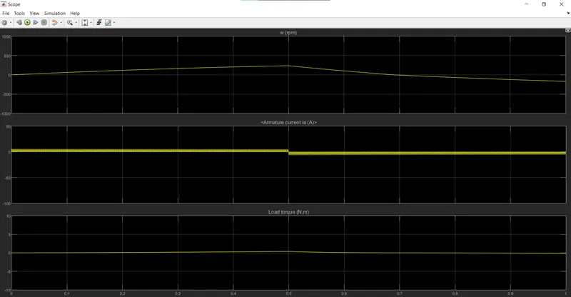
Hence changing the value to 35% we observe that the armature current does not increase suddenly.
2. Refer to help section of ‘The Four-Quadrant Chopper DC Drive (DC7) block’. Compare it with H-bridge model.
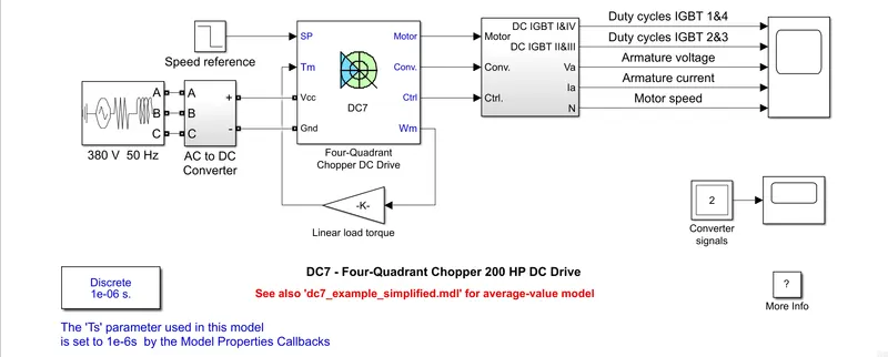
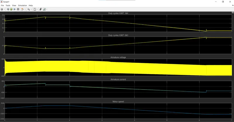
The four quadrant chopper drives works in 4 modes i.e
- Forward motoring mode (First quadrant)
- Forward regenerative braking mode (Second quadrant)
- Reverse motoring mode (Third quadrant)
- Reverse regenerative braking mode (Fourth quadrant)
In electronics, a chopper circuit is used to refer to numerous types of electronic switching devices and circuits used in power control and signal applications. A chopper is a device that converts fixed DC input to a variable DC output voltage directly. Essentially, a chopper is an electronic switch that is used to interrupt one signal under the control of another.
In power electronics applications, since the switching element is either fully on or fully off, its losses are low and the circuit can provide high efficiency. However, the current supplied to the load is discontinuous and may require smoothing or a high switching frequency to avoid undesirable effects. In signal processing circuits, use of a chopper stabilizes a system against drift of electronic components
Working
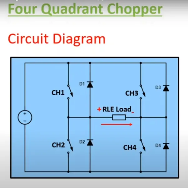
Forward Motoring Mode
In this mode the CH1 and CH4 are in the operating condition. The current then flows in the forward direction i.e positive and the voltage applied is also positive. While the current is flowing in this case, it charges the inductor present in the RLE load. Afterwards the CH1 is turned off and CH4 is still in on mode. Now the current flows from D2 to RLE load to CH4.
Forward Regenerative Braking mode
In this mode the CH2 is turned on and CH4 is turned off. The armature current will be reversed i.e now the current will flow from CH2 to D4 to RLE load. Here the current is in the opposite direction but the voltage is still positive. This will be in the second quadrant
Reverse Motoring Mode
In this mode CH3 and CH2 will be in operating condition. Here the current will flow from source voltage to CH3 to RLE load to CH2. Here the voltage will be negative and the current will also be negative. Therefore this will be hatched in the third quadrant.4
Reverse regenerative Braking Mode
Here CH4 is only turned on and the current will flow from CH4 to D2 to RLE load. Here the current is flowing in positive direction. When CH4 is turned off then the current will flow from D2 to RLE load to D3 to source voltage. Here the voltage is seen negative and this will be hatched in the fourth quadrant
Comparison between the four-quadrant chopper drive and H-Bridge
In Four-Quadrant chopper drive the motor can operate in all the four modes whereas in an H-bridge the motor operates in only two modes
Regenerative braking is achieved in a Four-Quadrant chopper drive whereas it is not possible in an H-Bridge
The Four-Quadrant chopper drive gives high efficiency than the H-Bridge model
3. Make a suitable EV model using DC7 block and make result report.
Here the speed reference block is not replaced
The AC-DC converter block is replaced by a voltage source block
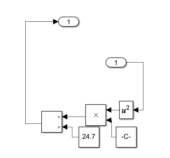
And the Linear load torque block is replaced by the Torque-speed characteristics which is given as below
`T = 24.7 + 0.0051*omega^2`
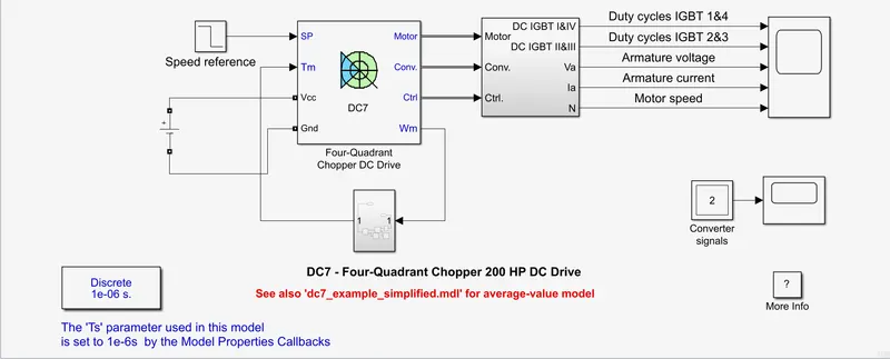
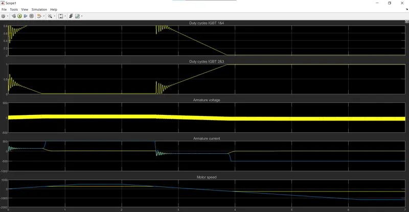
As we observe that when the speed of the motor increases, Duty cycle of IGBT 1 & 4 increases whereas Duty cycle of IGBT 2 & 3 decreases
Also it is observed that with an increase in the speed of the motor the armature current and voltage also increases and vice verca