Week 7 Challenge - Assembly Workbench
week 7 challenge:
Aim:
to create a part drawing of the given 2 drawing parts and assemble them together in the catia V5.
software used:
Catia V5
Procedure:
- open the dassault catia v5 software.
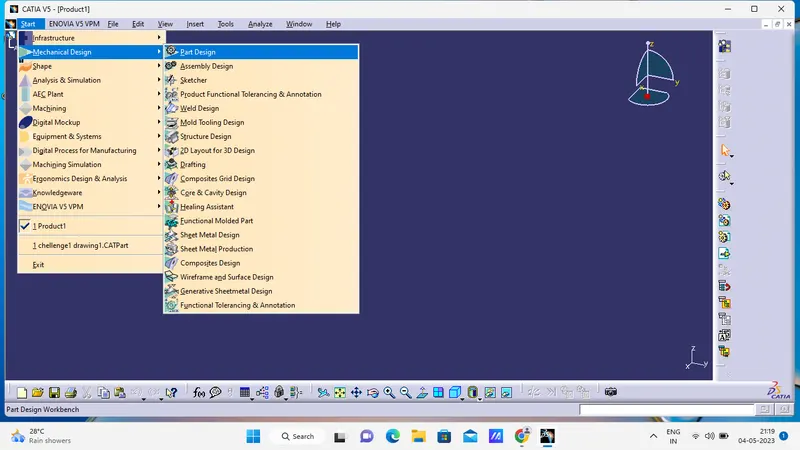
- then click on start >mechanical design>part design.
- now click on the geomentrical set on the dialog box.
- create a point in the origin. now from the inserts> sketcher> positioned sketcher as shown in below,
- to create a positioned sketch model. then create the drawing 1 and exit the sketch .
- save the CATpart file.
positioned sketch::
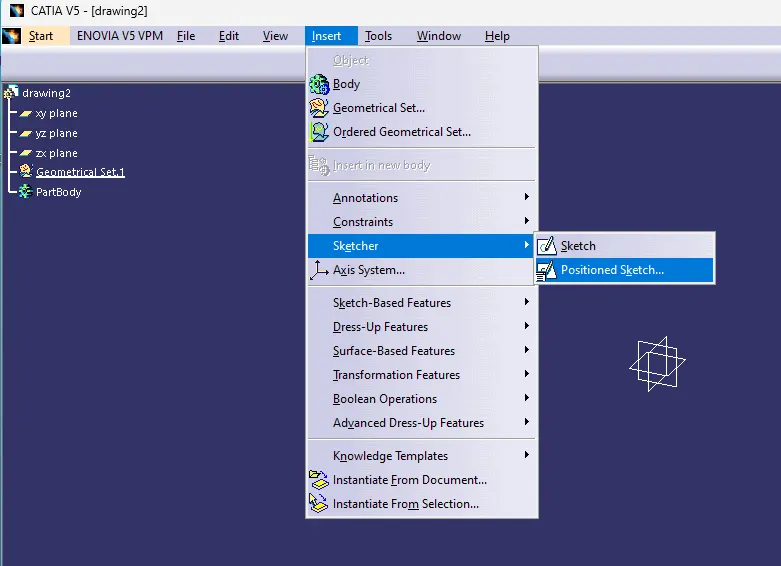
by using this method we can create a positioned sketch. by this only the part design of the two diagram was drawn.
PART DRAWING:
diagram 1:
for this the part body has been created like the below:
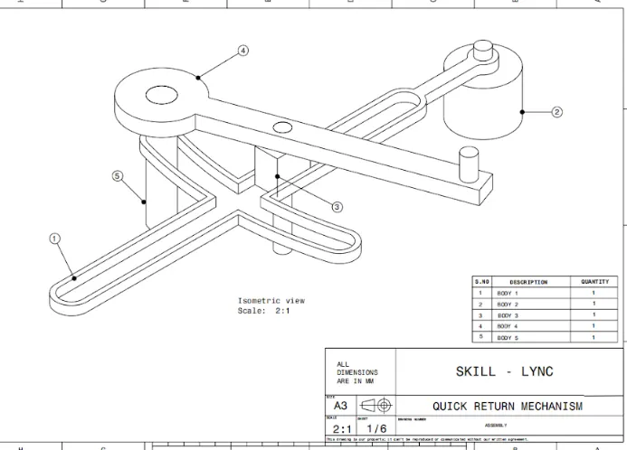
for this assembly, it is to create a five part diagram.
then, needed to assembly.
first , individually create a parts one by one by using a part workbench.
the five parts are shown below:
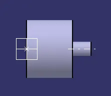
1) bush:
2) frame:
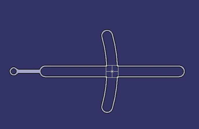
3) pin with square bush
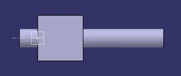
4) top piece
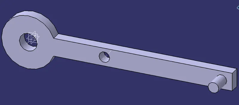
5) pin:
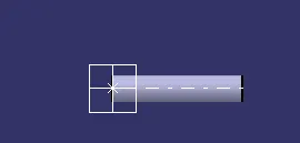
after creating this part. then the assembly of these parts are to be done.
first open the assembly work bench by the folowing method:
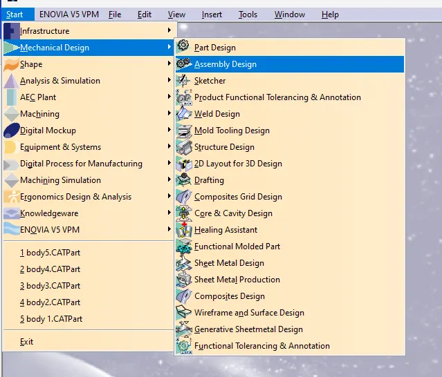
then copy paste the part into the assembly workbench.
intially create a skeleton part in the product workbench and fix it.
it should be considered as a referance .
then create a axis for all the parts.
then publication the axis,plane and point of all the parts.
by using a manipulation tools in product workbench.
it can move translate the parts to required position.
using a coincide,offset,contact surface. asemble the parts together like the below shown figure.
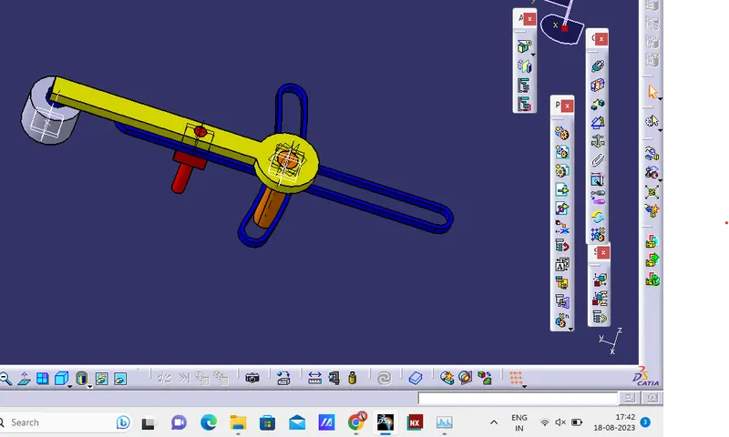
after creating using a save management save all the files in the same directory.
-----------------------------------------------------------------
diagram 2:
for this the part body has been created like the below:
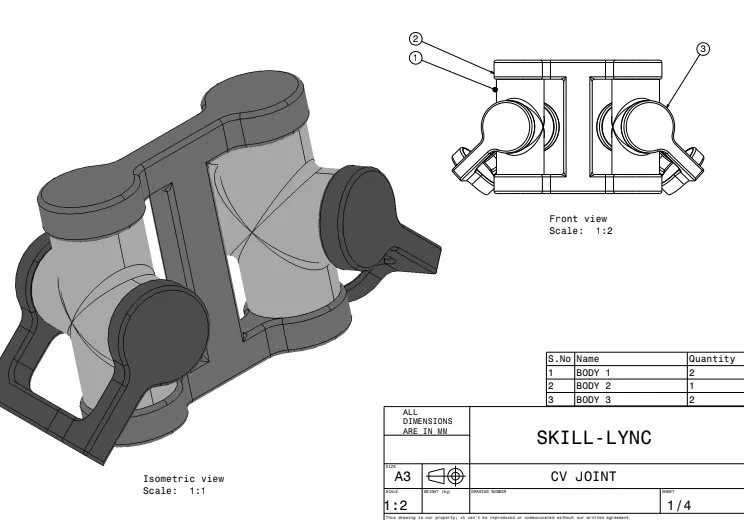
for this assembly, it is to create a five part diagram.
then, needed to assembly.
first , individually create a parts one by one by using a part workbench.
the five parts are shown below:
For this the part body has been created like the below.
1) plus bush
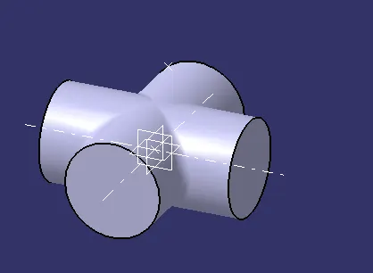
2)brackets:
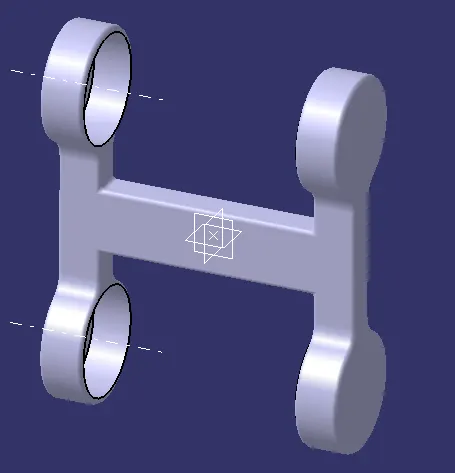
3) loose barcket:
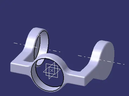
after creating this part. then the assembly of these parts are to be done.
first open the assembly work bench by the folowing method:
then copy paste the part into the assembly workbench.
intially create a skeleton part in the product workbench and fix it.
it should be considered as a referance .
then create a axis for all the parts.
here for same part to be copied. you need to copy the part and paste in the prouct.
then publication the axis,plane and point of all the parts.
by using a manipulation tools in product workbench.
it can move translate the parts to required position.
using a coincide,offset,contact surface. asemble the parts together like the below shown figure.
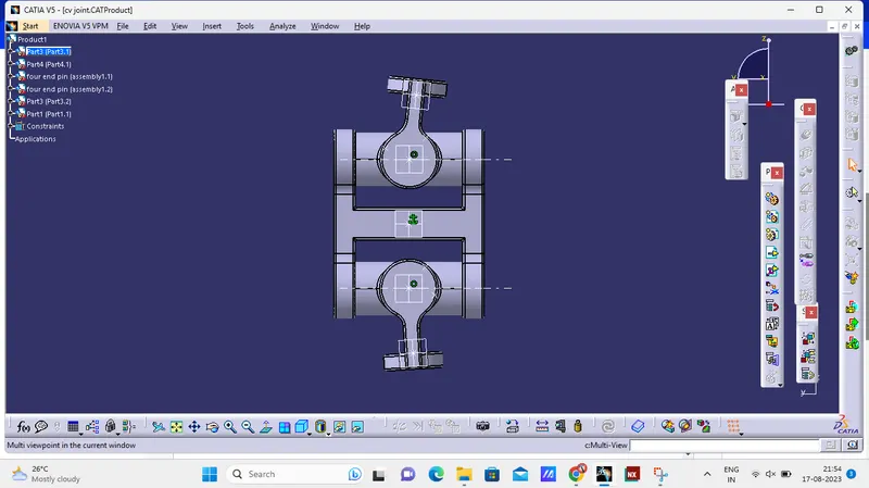
after creating using a save management save all the files in the same directory.
drafting of the assembly:
drawing 1:
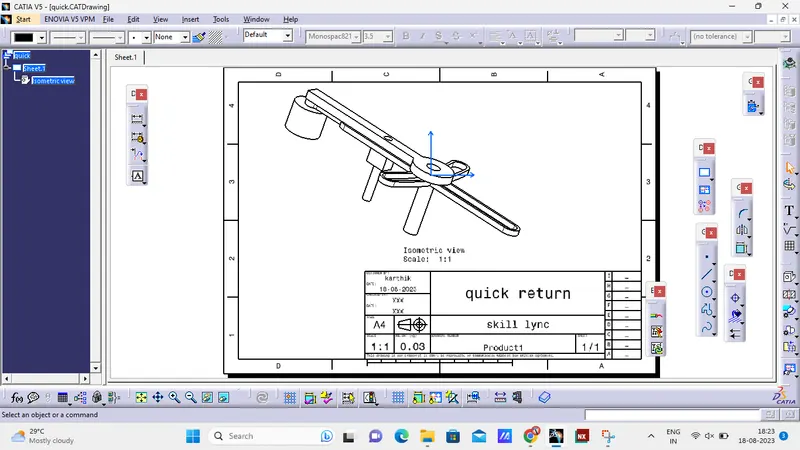
drawing 2:
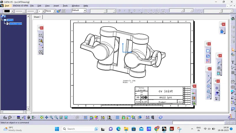
------------------------------------------------------------------
the above shown part and product drawing is attached.
the attached file contains:
drawing 1: 5 parts and 1 product.
drawing 2: 3 parts and 1 products.
drafting of these 2 drawing.
=====================================
thank you!!!