Week 7 Challenge - Assembly Workbench
Theory of Quick Return Mechanism and its Assembly in CATIA
1. Introduction
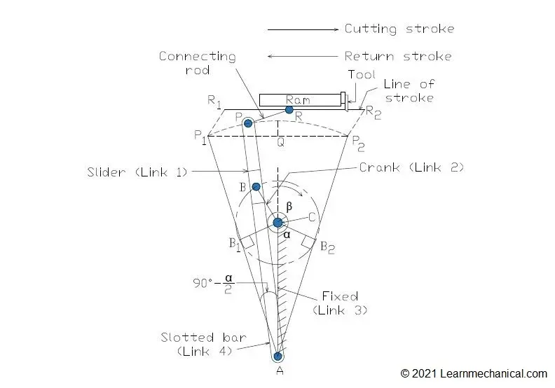
The Quick Return Mechanism (QRM) is a type of slider-crank mechanism that converts rotary motion into reciprocating motion with different speeds for the forward and return strokes. This mechanism is widely used in shaping machines, slotting machines, and mechanical presses where a slow cutting stroke (forward) and a fast return stroke are required for efficiency.
2. Working Principle
The mechanism consists of the following key components:
- Crank (Body 2) – Rotates with a constant angular velocity (connected to a motor or power source).
- Slider/Block (Body 3) – Connects the crank to the rocker arm, allowing sliding motion.
- Rocker Arm (Body 4) – Converts rotary motion into oscillatory motion.
- Ram/Tool Holder (Body 5) – The output component that performs the reciprocating motion.
- Fixed Frame (Body 1) – Provides structural support for all moving parts.
Why is it called "Quick Return"?
- The mechanism is designed such that the forward (cutting) stroke is slower (more time) while the return stroke is faster (less time).
- This is achieved due to the asymmetrical motion of the crank and rocker arm geometry.
3. Assembly Process in CATIA
Step 1: Creating Individual Parts
Before assembling, each component (Body 1 to Body 5) must be modelled separately in CATIA Part Design.
- Body 1 (Base Frame) – Stationary part with mounting holes and guideways.
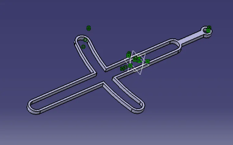
- Body 2 (Crank) – Rotating part connected to the motor.
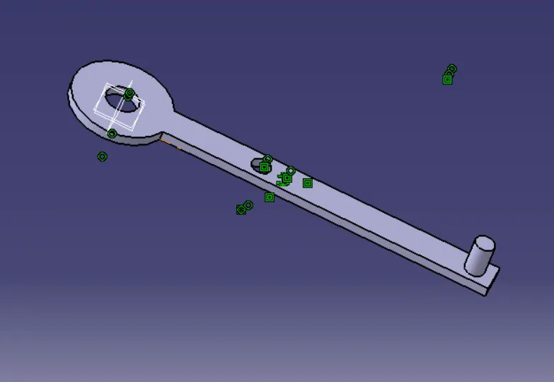
- Body 3 (Slider/Connecting Block) – Links the crank to the rocker arm.
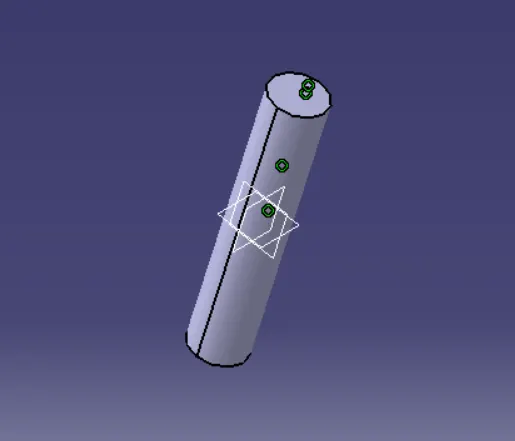
- Body 4 (Rocker Arm) – Oscillates to convert motion.
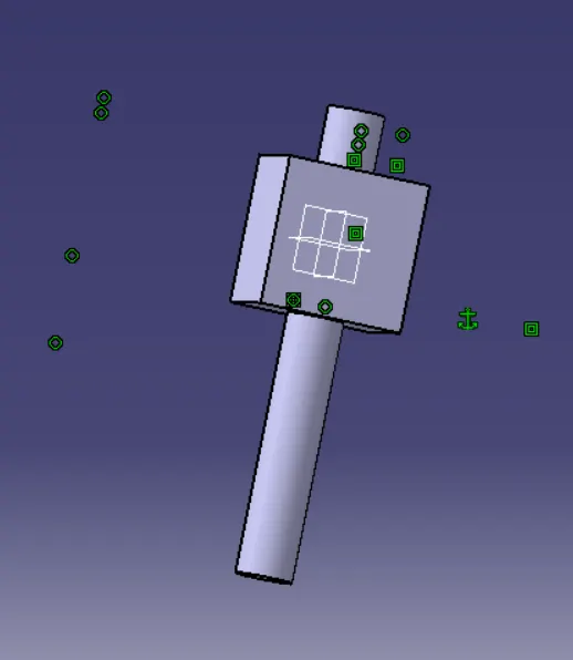
- Body 5 (Ram/Tool Holder) – Moves linearly for the cutting operation.
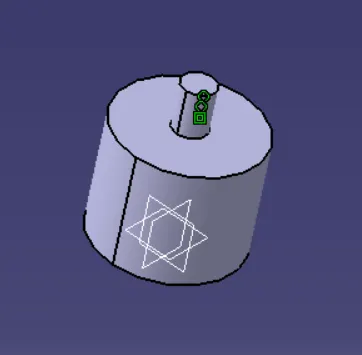
Step 2: Creating the Assembly (Product File)
- Open a new Product file in CATIA.
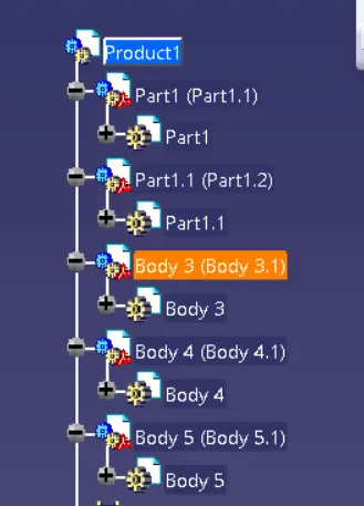
- Use the "Existing Component" option to insert all parts (Body 1 to Body 5).
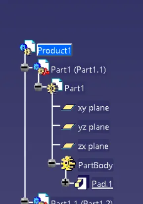
Step 3: Applying Constraints
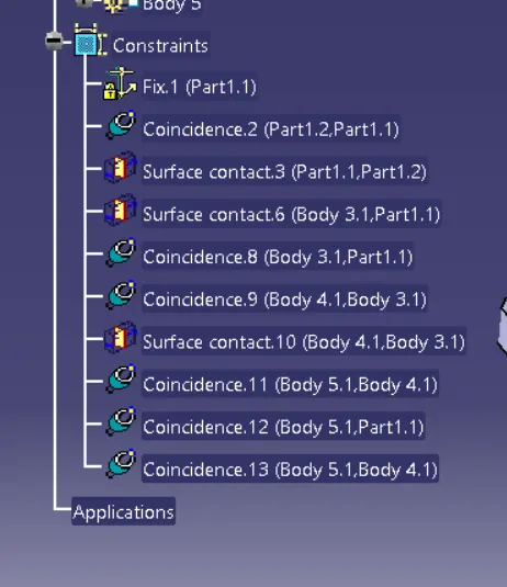
- Fix Body 1 (Base Frame) – This prevents movement and serves as a reference.
- Coincidence Constraint (Body 1 & Body 2)
- Align the rotational axis of the crank with the bearing hole in the base.
- Apply face coincidence to ensure proper alignment.
- Coincidence Constraint (Body 2 & Body 3 – Slider)
- The slider must move along the crank’s rotation.
- Coincidence Constraint (Body 3 & Body 4 – Rocker Arm)
- Ensures the slider connects properly to the rocker arm.
- Coincidence Constraint (Body 4 & Body 5 – Ram)
- The rocker arm must drive the ram in a straight-line motion.
Step 4: Verification Using Exploded View
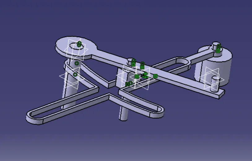
- After applying all constraints, use the "Explode" tool to check if all parts are properly constrained.
- If parts move correctly in relation to each other, the assembly is successful.
4. Applications of Quick Return Mechanism
- Shaping Machines – Used for metal cutting with a slow forward stroke and fast return.
- Slotting Machines – Vertical cutting operations.
- Mechanical Presses – Enhances productivity by reducing idle time.
- Automated Packaging Machines – For intermittent motion control.
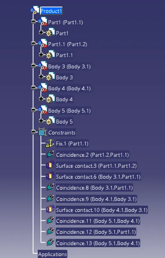
5. Complete Tree of Quick Return Mechanism Assembly
5. Conclusion
The Quick Return Mechanism is an efficient way to achieve asymmetrical reciprocating motion. By assembling it in CATIA, we ensure proper fit and function before manufacturing. The use of coincidence constraints and exploded view verification helps in validating the mechanism’s kinematics.
This mechanism is crucial in industrial applications where time efficiency and controlled motion are required.
References
- Machine Design Theory (R.S. Khurmi)
- CATIA V5 Assembly Design Manual
- Kinematics of Machinery (Norton)