Week 7 Challenge - Assembly Workbench
Week 7 Challenge - Assembly Workbench
*AIM ....
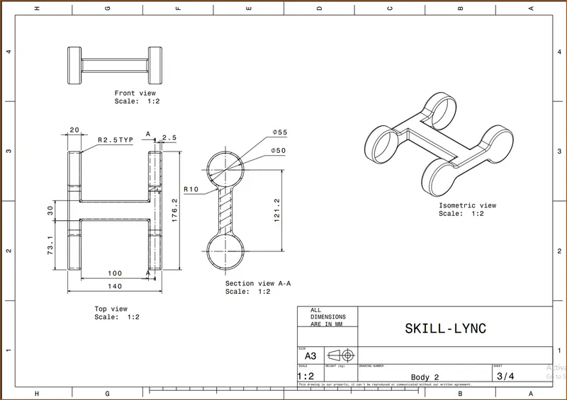
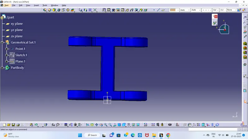
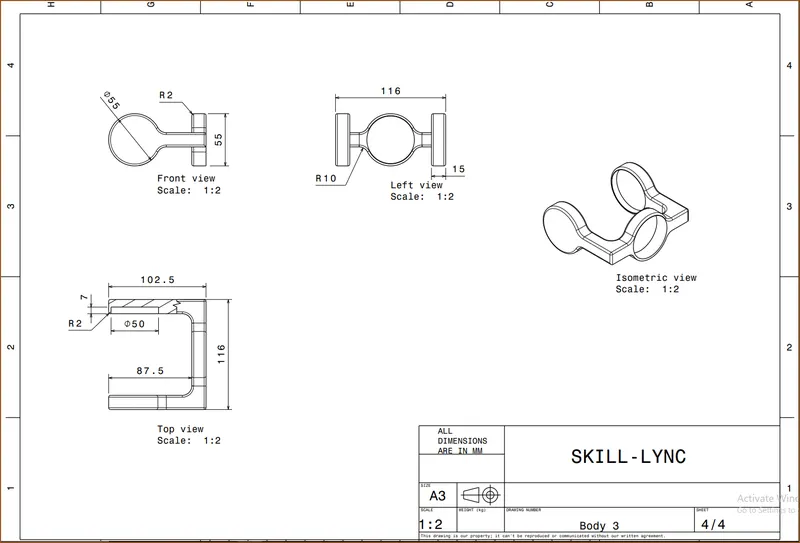
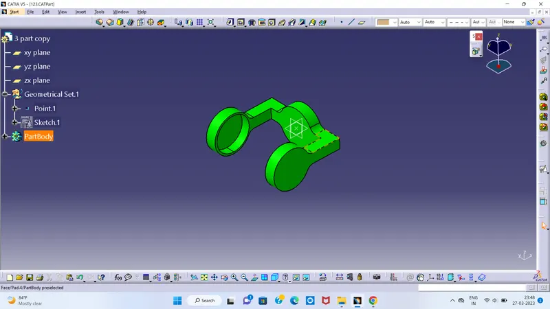
To create 2 assemblies according to the content provided with 2D diagrams of the components by first creating the individual part files and then create a complete assembly of those part files in the assembly workbench. After creating the assembly make use of the drafting tools to create a 2D drawing similar to the assembly parts.
*THEORY .....
Assembly modeling is the process of creating designs that consist of two or more components assembled together at their respective work positions. The components are brought together and assembled in Assembly Design workbench by applying suitable parametric assembly constraints to them. The assembly constraints allow you to restrict the degrees of freedom of components on their respective work positions.
*ASSEMBLY WORKBENCH .....
The assembly files in CATIA are called Product files. There are two methods to invoke the Assembly Design workbench of CATIA. The primary method to start a new product file is by selecting File > New from the menu bar to open the New dialog box From this dialog box select Product. The other method of invoking the Assembly Design workbench is by choosing Start > Mechanical Design > Assembly Design from the menu bar.
PROCEDURE ....
STEP 1 - CREATING BOTTOM-UP ASSEMBLIES :
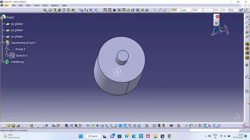
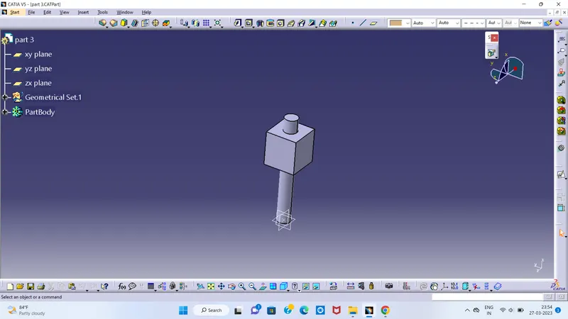
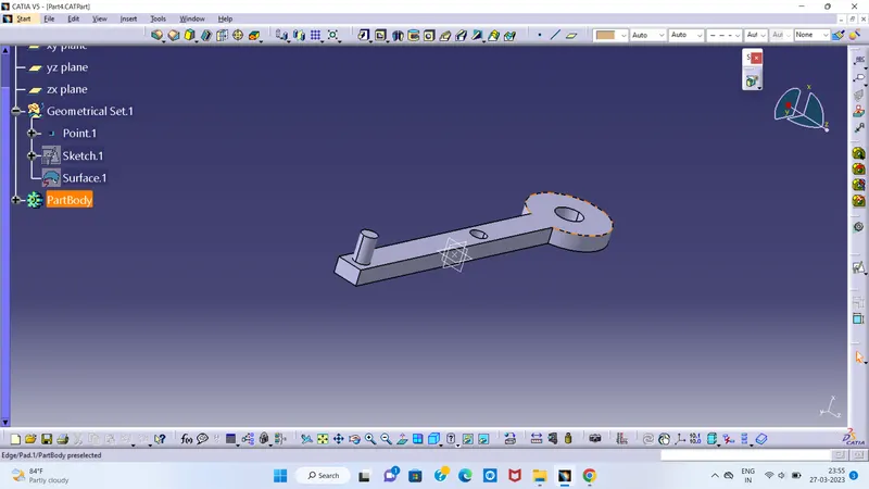
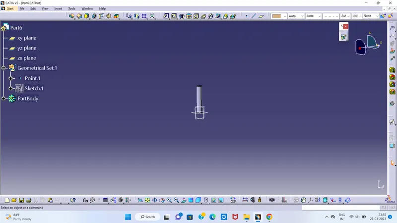
As mentioned earlier, while creating an assembly using the bottom-up approach, the components are created in separate part files and are then inserted into the assembly file. They are assembled at their working position by applying assembly constraints to them. To create an assembly using this approach, it is recommended to insert the first component and fix its position after properly orienting it in the 3D space. The other components can be inserted and positioned with reference to the first component. The method used for placing components inside the product file is discussed below.
Now we will create a CV joint assembly which consists of 5 parts in which few parts are identical which we can duplicate/copy later
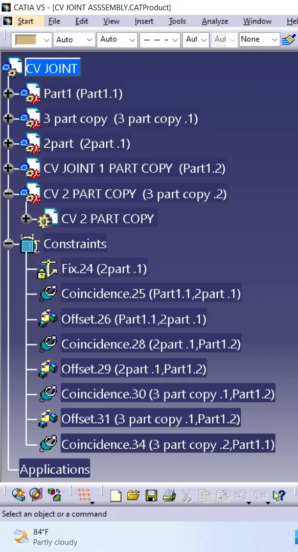
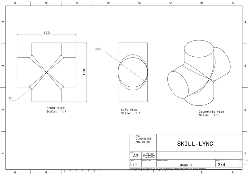
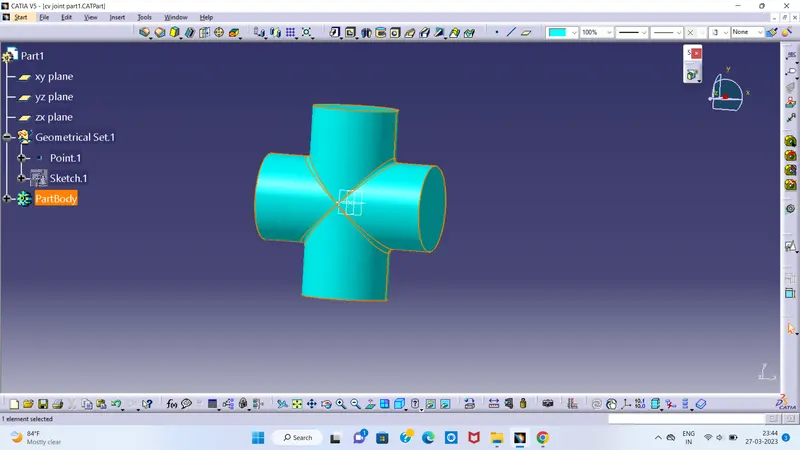
ASSEMBLY WORBUNCH USING
USING COMMENTS
FIXED CONSTRAIN
CONTACT CONSTRAIN
OFFSET CONSTRAIN
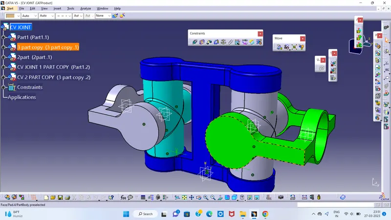
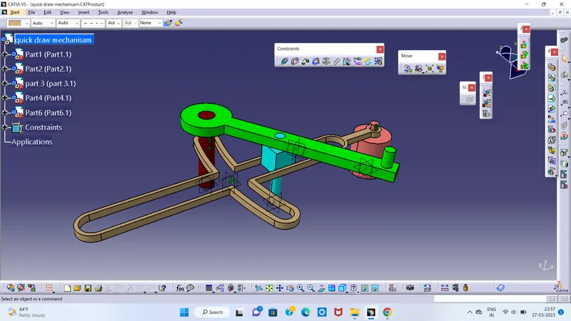
ASSEMBLY 2 : QUICK RETURN MECHANISM
Quick return mechanism -
A quick return mechanism is an apparatus that consists of a system of links with 3 turning pairs and a sliding pair that can convert rotary motion into reciprocating motion. The time taken for travel in return stroke is less than in forward stroke.A quick return mechanism is also known as Crank and slotted lever quick return motion mechanism.
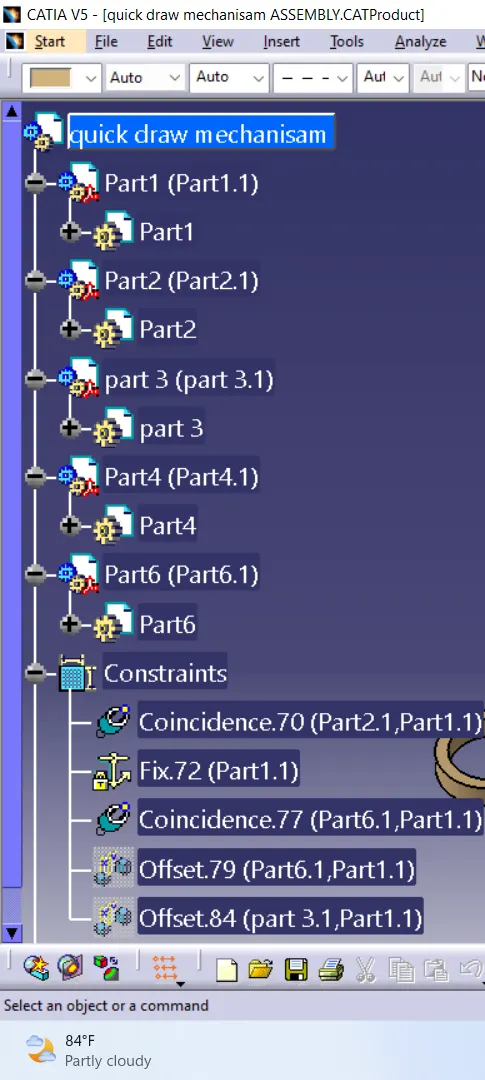
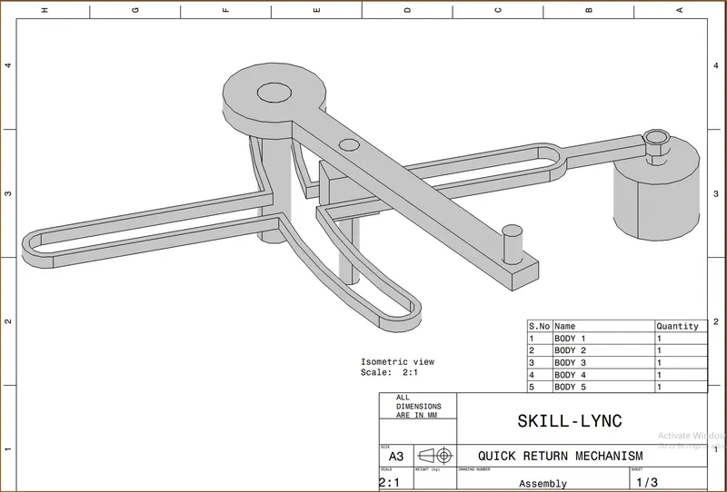
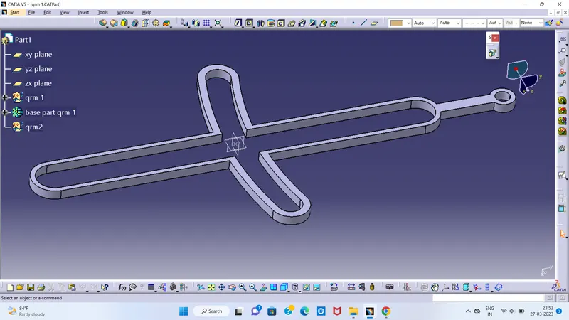
ASSEMBLY WORBUNCH USING
USING COMMENTS
FIXED CONSTRAIN
CONTACT CONSTRAIN
OFFSET CONSTRAIN