Week 7 Challenge - Assembly Workbench
ASSEMBLY WORKBENCH
QUICK RETURN MECHANISM
& CV JOINT DESIGN
- AIM: -
To create a 3 D Solid CAT Part files using 2 D Sketch, also to solve the sketches with fully (ISO) constrained and also to create a 2 D Drafting sheet from the solid CAT part and Assembly Product with the Frame and Tittle Block.
- Objective: -
- To draw the 2-D sketch in CATIA by using the Positioned sketch in Sketcher Workbench.
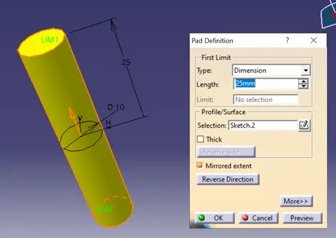
- To create a Solid CAT Part using Part Workbench with Sketch based feature and Dress up features.
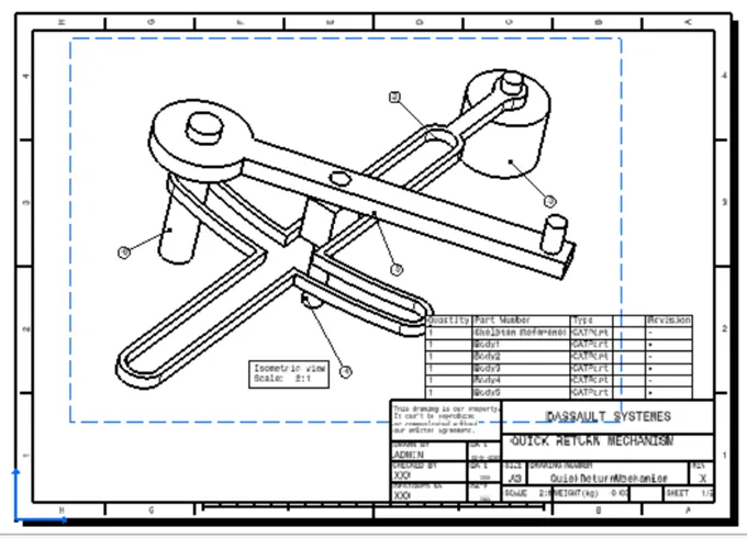
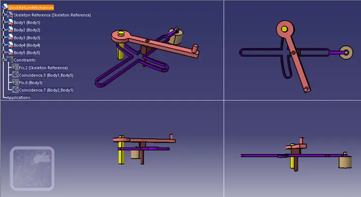
- To create a complete Assembly for Quick Return Mechanism using Assembly Workbench.
- To create a complete Assembly for CV Joint using Assembly Workbench.
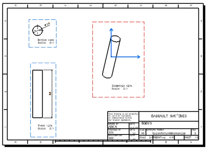
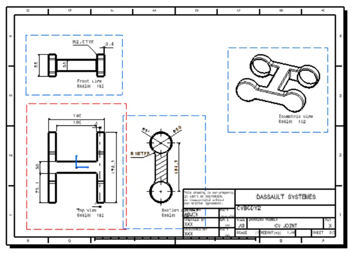
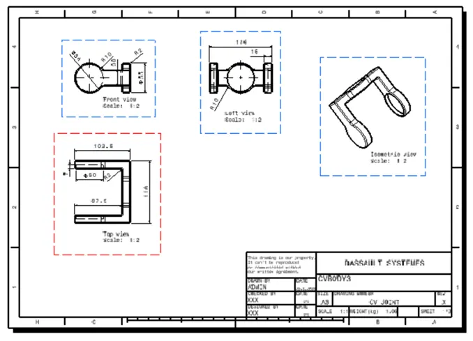
- To create a 2D Draft sheet using Drafting workbench.
- To follow the Design standards and to align the views in a proper way.
- To Import the Frame/Border and Tittle Block in the 2D draft sheet to locate the drawing inside the sheet to guide.
- To Dimensionate the 2D using the feature in the Drafting workbench.
- Introduction: -
Assembly workbench:
The Assembly Workbench uses constraints and expressions to create relationships between objects in your model and mathematically bind them in place.
Components are assembled and assembled in the Assembly Design workbench by applying appropriate parametric assembly constraints. Assembly constraints let you constrain the degrees of freedom of components to their working positions. CATIA assembly files are called product files.
Constraints:
Constraints are used to lock degrees of freedom (DOF) in translational and rotational motion along the x, y, and z axes. Constraints can also be applied manually after placing the sketch geometry to stabilize the shape or position of the sketch.
TYPES OF CONSTRAINTS:
- Dimensional Constraints.
- Geometrical Constraints.
- DIMENSIONAL CONSTRAINT:
A dimensional constraint is a constraint whose value determines geometric object measurement.
For example: It control the length of a line, or the distance between two points.
- GEOMETRICAL CONSTRAINT:
A geometric constraint is a relationship that forces a limitation between one or more geometric elements.
For example: A geometric constraint requires that two lines be parallel. If three lines are selected, or two lines and a point, these elements will automatically result parallel to each other.
DRAFTING:
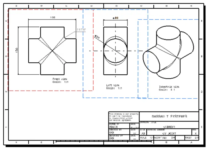
The Drafting is a engineering drawing, graphical representation of structures, machines, and their component parts that communicates the engineering intent of a technical design to the craftsman to makes the product.
PROJECTIONS:
Projection methods are used to represent a 3D object in simple terms so that it can be understood more easily. It’s used in mechanical drawing and design so that the structure created by a designer can be communicated to manufacturers.
FRAMES AND TITTLE BLOCK:
A border/ Frame is a line drawn around the inside edge of the paper. It is basically a rectangle drawn precisely and inside this rectangle is the design area.
A title block is comprised of the information boxes found on the bottom right- hand corner of a drawing, which indicate drawing details such as the title, author name, scale, and date the drawing was created and informations.
POSITIONED SKETCH:
A Positioned Sketch is a sketch that has its origin location or orientation defined with construction geometry. As the construction geometry changes the sketch position or orientation will change accordingly.
Creation of 3D parts & assemblies:
- Quick Return Mechanism:
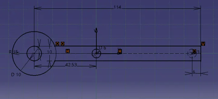
All the degrees of freedom of a geometry have been taken up by a consistent combination of dimensions and fixed geometry, that geometry is said to be iso-constrained/ fully defined.
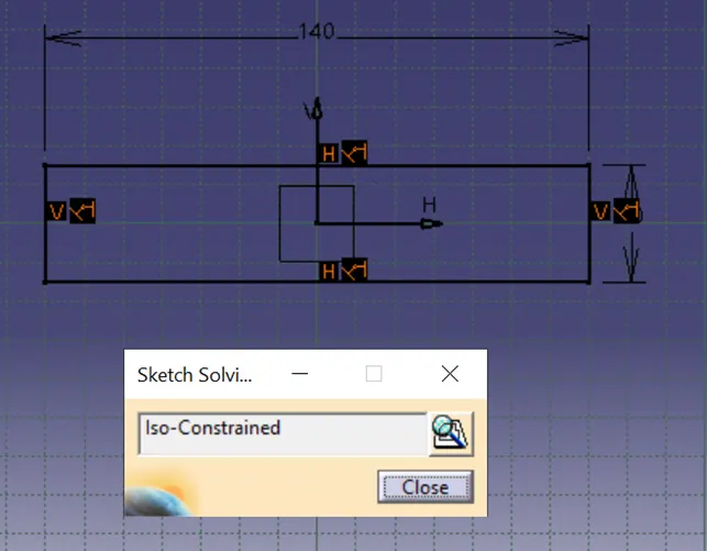
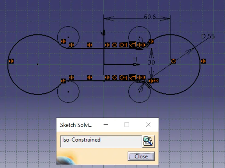
In two dimensions, points and lines have two degrees of freedom, circles have three and ellipses have five degrees of freedom. Fixed geometry will never be moved, and has no degree of freedom. Arresting all DOF from the origin then the sketch will be iso-constrained.
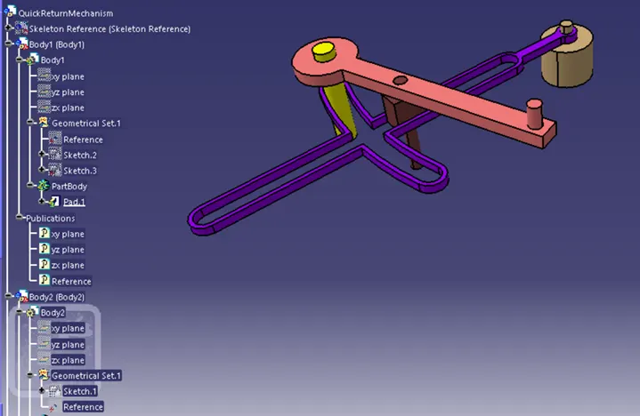
BODY 1:-
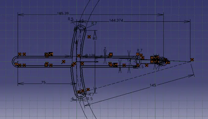
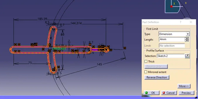
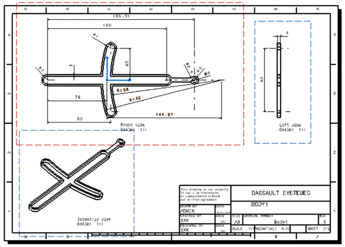
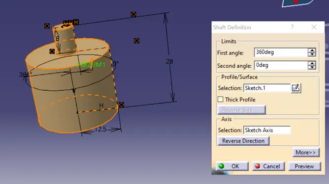
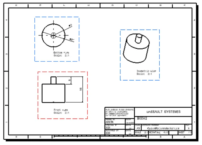
BODY 2:-
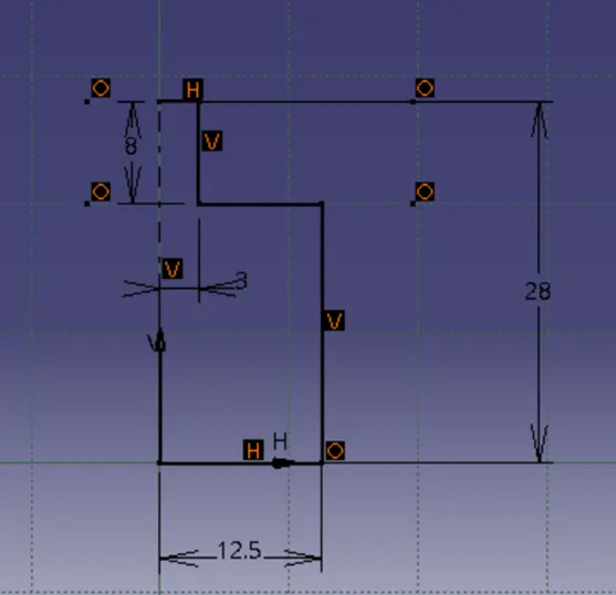
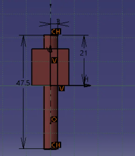
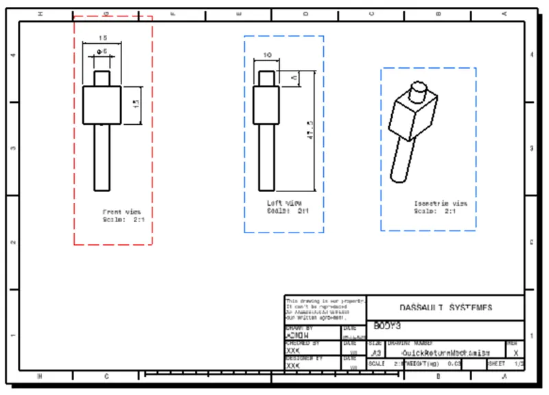
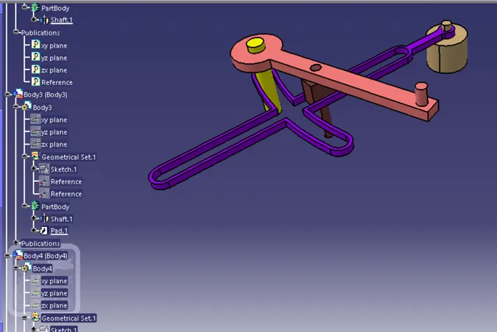
BODY 3:-
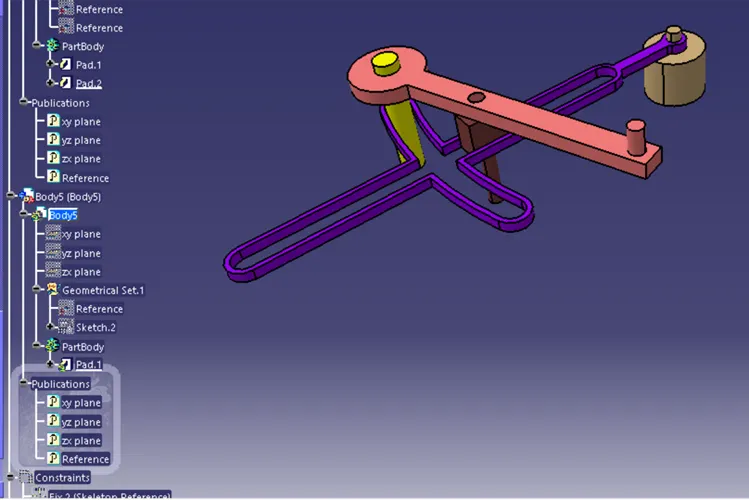
BODY 4:-
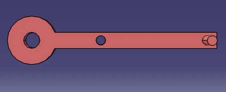
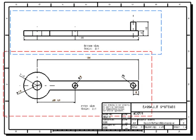
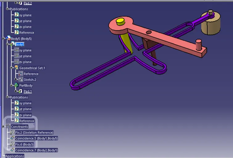
BODY 5:-
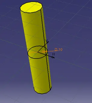
Quick Return Mechanism Assembly: -
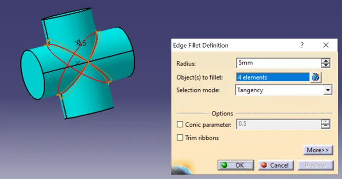
- CV Joint:
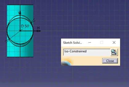
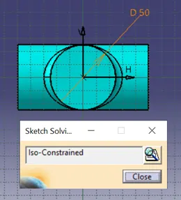
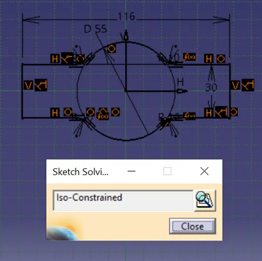
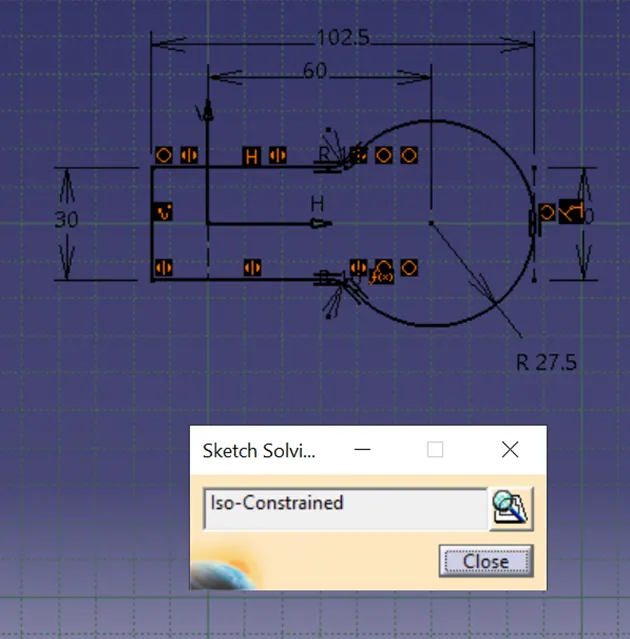
All the degrees of freedom of a geometry have been taken up by a consistent combination of dimensions and fixed geometry, that geometry is said to be iso-constrained/ fully defined.
In two dimensions, points and lines have two degrees of freedom, circles have three and ellipses have five degrees of freedom. Fixed geometry will never be moved, and has no degree of freedom. Arresting all DOF from the origin then the sketch will be iso-constrained.
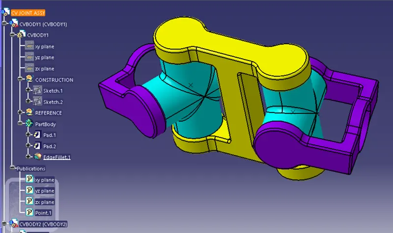
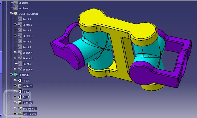
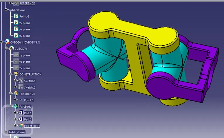
BODY 1:-
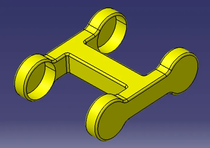
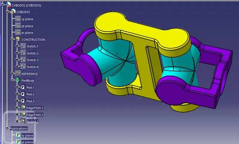
BODY 2:-
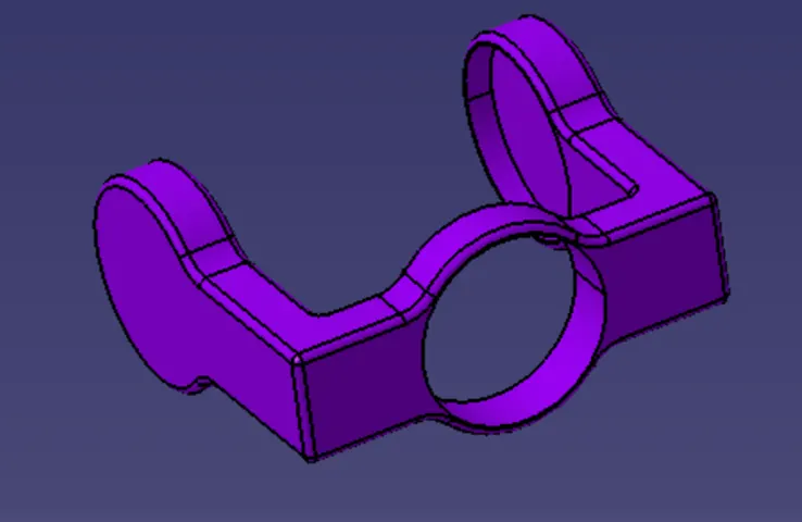
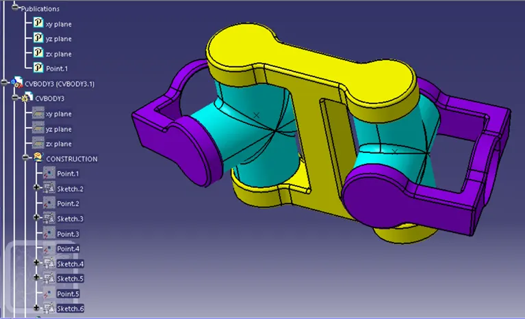
BODY 3:-
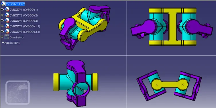
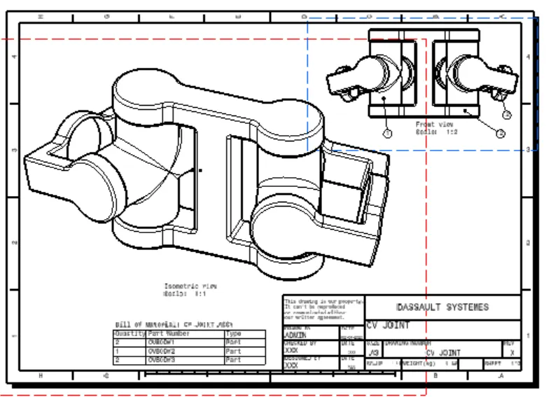
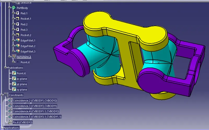
CV JOINT ASSEMBLY:-
- Conclusion: -
The ASSEMBLY WORKBENCH assignment of Quick return mechanism & CV Joint design w.r.t. reference drawings provided & 3D design drafting also done completely with the help of CATIA software.