Week 7 Challenge
Aim:-
To Explain How to fix no. of piles in the deep foundations.
To Explain the different factors that can impact the number of piles and its depth and it is different in wall type abutment and pier (free and fix).
To Explain How to fix the diameter of well in the deep foundation.
To Explain the impact of free-standing length on the full length of the pile and calculate Roughly determine no. of piles.
List out failures in deep foundations and construction
How to fix no. of piles in the deep foundation:-
Load applied from structure to the foundation
- Bearing capacity of soil.
- Depth of water level below the ground surface.
- Types of soil and depth of layers in case of layered soil.
- Depth of adjacent foundation.
Listing all the loads acting:-
- all the loads acting
- Self-weight
- Buoyancy
- A dead load of the superstructure
- A dead load of bearing and piers
- Force on account of the resistance of the bearing against movement due to change in temperature.
- Force due to flowing water.
- Wind pressure.
- Seismic force
- Earth Pressure
List of all loads acting on the flyover:-
Various design loads to be considered in the design of bridges are:-
- Dead load
- Live load
- Impact load
- Wind load
- Longitudinal forces
- Centrifugal forces
- Buoyancy effect
- Effect of water current
- Thermal effects
- Deformation and horizontal effects
- Erection stresses
- Seismic loads
- Dead Load
The dead load is nothing but a self-weight of the bridge elements. The different elements of bridge are deck slab, wearing coat, railings, parapet, stiffeners and other utilities. It is the first design load to be calculated in the design of bridge.
- Live Load
The live load on the bridge, is moving load on the bridge throughout its length. The moving loads are vehicles, Pedestrians etc. but it is difficult to select one vehicle or a group of vehicles to design a safe bridge. So, IRC recommended some imaginary vehicles as live loads which will give safe results against the any type of vehicle moving on the bridge. The vehicle loadings are categorized in to three types and they are
- IRC class AA loading
- IRC class A loading
- IRC class B loading
IRC Class AA Loading
This type of loading is considered for the design of new bridge especially heavy loading bridges like bridges on highways, in cities, industrial areas etc. In class AA loading generally two types of vehicles considered, and they are
- Tracked type
- Wheeled type
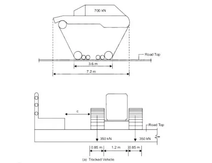
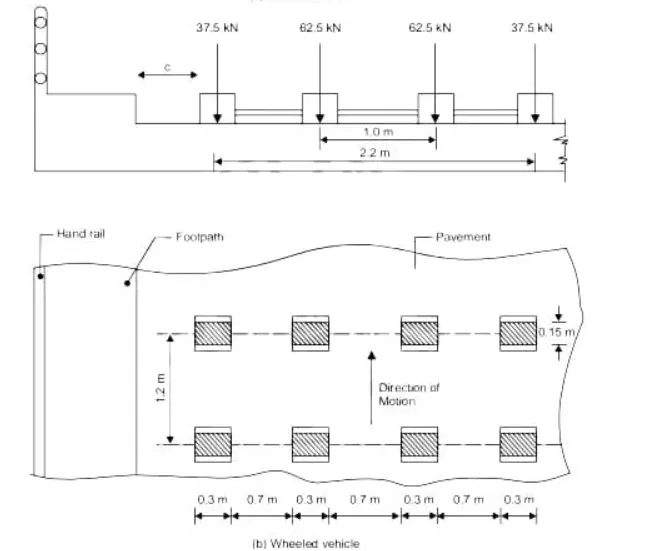
IRC Class A Loading
This type of loading is used in the design of all permanent bridges. It is considered as standard live load of bridge. When we design a bridge using class AA type loading, then it must be checked for class A loading also.
IRC Class B Loading
This type of loading is used to design temporary bridges like Timber Bridge etc. It is considered as light loading. Both IRC class A and Class B .
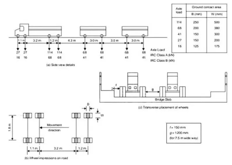
- Impact Loads
The Impact load on bridge is due to sudden loads which are caused when the vehicle is moving on the bridge. When the wheel is in movement, the live load will change periodically from one wheel to another which results the impact load on bridge. To consider impact loads on bridges, an impact factor is used. Impact factor is a multiplying factor which depends upon many factors such as weight of vehicle, span of bridge, velocity of vehicle etc. The impact factors for different IRC loadings are given below.
For IRC Class AA Loading and 70R Loading
| Span | Vehicle type | Impact factor |
| Less than 9 meters | Tracked vehicle | 25% up to 5m and linearly reducing to 10% from 5 m to 9 m. |
| Wheeled vehicle | 25% up to 9 m | |
| Greater than 9 meters | Tracked vehicle (RCC bridge) | 10% up to 40 m |
| Wheeled vehicle (RCC bridge) | 25% up to 12m | |
| Tracked vehicle (steel bridge) | 10% for all spans | |
| Wheeled vehicle (steel bridge) | 25% up to 23m |
For IRC class A and class B loadings
Impact factor If = A/(B+L)
Where L = span in meters A and B are constants
| Bridge type | A | B |
| RCC | 4.5 | 6.0 |
| Steel | 9.0 | 13.50 |
Apart from the super structure impact factor is also considered for substructures
For bed blocks, If = 0.5
For substructure up to the depth of 3 meters If = 0.5 to 0
For substructure greater than 3 m depth If = 0
- Wind Loads
Wind load also an important factor in the bridge design. For short span bridges, wind load can be negligible. But for medium span bridges, wind load should be considered for substructure design. For long span bridges, wind load is considered in the design of super structure.
- Longitudinal Forces
The longitudinal forces are caused by braking or accelerating of vehicle on the bridge. When the vehicle stops suddenly or accelerates suddenly it induces longitudinal forces on the bridge structure especially on the substructure. So, IRC recommends 20% of live load should be considered as longitudinal force on the bridges.
- Centrifugal Forces
If bridge is to be built on horizontal curves, then the movement of vehicle along curves will cause centrifugal force on to the super structure. Hence, in this case design should be done for centrifugal forces also. Centrifugal force can be calculated by C (kN/m) = (WV2)/(12.7R)
Where
W = live load (kN)
V = Design speed (kmph)
R = Radius of curve (m)
- Buoyancy Effect
Buoyancy effect is considered for substructures of large bridges submerged under deep water bodies. Is the depth of submergence is less it can be negligible.
- Forces by Water Current
When the bridge is to be constructed across a river, some part of the substructure is under submergence of water. The water current induces horizontal forces on submerged portion. The forces caused by water currents are maximum at the top of water level and zero at the bottom water level or at the bed level.
The pressure by water current is P = KW [V2/2g]
Where P = pressure (kN/m2)
K = constant (value depending upon shape of pier)
W = unit weight of water
V = water current velocity (m/s)
G = acceleration due to gravity (m/s2)
- Thermal Stresses
Thermal stresses are caused due to temperature. When the temperature is very high or very low they induce stresses in the bridge elements especially at bearings and deck joints. These stresses are tensile in nature so, concrete cannot withstand against this and cracks are formed. To resist this, additional steel reinforcement perpendicular to main reinforcement should be provided. Expansion joints are also provided.
- Seismic Loads
When the bridge is to be built in seismic zone or earthquake zone, earthquake loads must be considered. They induce both vertical and horizontal forces during earthquake. The amount of forces exerted is mainly depends on the self-weight of the structure. If weight of structure is more, larger forces will be exerted.
- Deformation and Horizontal Effects
Deformation stresses are occurred due to change is material properties either internally or externally. The change may be creep, shrinkage of concrete etc. similarly horizontal forces will develop due to temperature changes, braking of vehicles, earthquakes etc. Hence, these are also be considered as design loads in bridge design.
- Erection Stresses
Erection stress are induced by the construction equipment during the bridge construction. These can be resisted by providing suitable supports for the members.
Partial Safety Factor for Verification of Equilibrium
COMBINATION OF LOADS FOR LIMIT STATE DESIGN
- Dead Load
- Snow load
- Superimposed dead load such as hand rail, crash barrier, foot path and service
- Surfacing or wearing coat
- Back Fill Weight
- Earth Pressure
- Primary and secondary effect of prestress
- Secondary effects such as creep, shrinkage and
- Temperature effects including restraint and bearing
- Carriageway live load, footpath live load, construction live
- Associated carriageway live load such as braking, tractive and centrifugal
- Accidental forces such as vehicle collision load, barge impact due to floating bodies and accidental wheel load on mountable footway
- Wind
- Seismic Effect
- Construction dead loads such as weight of launching girder, truss or cantilever construction equipments
- Water Current Forces
- Wave Pressure
- Buoyancy
The Base Pressure and Design of Foundation:-
|
Loads |
Combination (1) |
Combination (2) |
Seismic Combination |
Accidental Combination |
|
(1) |
(2) |
(3) |
(4) |
(5) |
|
1. Permanent Loads: |
||||
|
1.1 Dead Load, Snow load (if present), SIDL except surfacing and Back Fill weight |
1.35 |
1.0 |
1.35 |
1.0 |
|
a) When causing adverse effects |
1.35 |
1.0 |
1.35 |
1.0 |
|
b) When causing Relieving effects |
1.0 |
1.0 |
1.0 |
1.0 |
|
1.2 Surfacing |
1.75 |
1.0 |
1.75 |
1.0 |
|
a) When causing adverse effect |
1.75 |
1.0 |
1.75 |
1.0 |
|
b) When causing relieving effect |
1.0 |
1.0 |
1.0 |
1.0 |
|
1.3 Prestress Effect |
(Refer Note ) |
|||
|
1.4 Settlement Effect |
1.0 or 0 |
1.0 or 0 |
1.0 or 0 |
1.0 or 0 |
|
1.5 Earth Pressure |
||||
|
a) Adding to the effect of variable loads |
1.50 |
1.30 |
1.0 |
1.0 |
|
b) Relieving the effect of variable loads |
1.0 |
0.85 |
1.0 |
1.0 |
|
2. Variable Loads: |
||||
|
2.1 All carriageway loads and associated loads (braking, tractive and centrifugal) and footway live load |
||||
|
a) Leading Load |
1.5 |
1.3 |
- |
0.75 (if applicable) or 0 |
|
b) Accompanying Load |
1.15 |
1.0 |
0.2 |
0.2 |
|
2.2 Thermal Load as accompanying load |
0.90 |
0.80 |
0.5 |
0.5 |
|
2.3 Wind Load |
||||
|
a) Leading Load |
1.5 |
1.3 |
- |
|
|
b) Accompanying Load |
0.9 |
0.8 |
0 |
0 |
|
2.4 Live Load surcharge as Accompanying Load (if applicable) |
1.2 |
1.0 |
0.2 |
0.2 |
|
3. Accidental Effect or Seismic Effect |
||||
|
a) During Service |
- |
- |
1.5 |
1.0 |
|
b) During Construction |
- |
- |
0.75 |
0.5 |
|
4. Construction Dead Loads |
1.35 |
1.0 |
1.35 |
1.0 |
|
5. Hydraulic Loads: |
||||
|
5.1 Water Current |
1.0 or 0 |
1.0 or 0 |
1.0 or 0 |
1.0 or 0 |
|
5.2 Wave Pressure |
1.0 or 0 |
1.0 or 0 |
1.0 or 0 |
1.0 or 0 |
|
5.3 Hydrodynamic effect |
- |
- |
1.0 or 0 |
|
|
6. Buoyancy: |
||||
|
a) For Base Pressure |
1.0 |
1.0 |
1.0 |
1.0 |
|
b) For Structural Design |
0.15 |
0.15 |
0.15 |
0.15 |
Type of factors to the number of piles and depth:-
- Type and loads from the superstructure.
- Properties of soil.
- The depth of the soil layer capable of supporting the piles.
- Variations in length of pile required.
- Availability of materials.
- Durability required.
- Available equipment for pile driving.
- Budget.
- The depth of water level and intensity of underground water flow.
- Types of surrounding structures.
Difference Between Wall type Abutment and pier:
Pier are the internal supports of the bridge. Abutments are the ends supports of the bridge. Pier can use more than two in bridge construction. Pier are constructed between the abutments.
|
Sr.No. |
Detail |
Pier |
Abutment |
|
1 |
Support |
The intermediate supports for the superstructure of a multi-span bridge are known as piers. |
The end supports of a bridge superstructure are known as abutments. |
|
2 |
Material |
A pier essentially consists of two parts i.e. a column shaft and the foundation. |
Abutments are built either with brick masonry, stone masonry, mass concrete, precast concrete blocks or RCC. |
|
3 |
Function |
The function of a pier is to transmit the load from the bridge to the underneath sub-soil. |
Abutments support the ends of the bridge and transfer the loads from the superstructure into the ground. |
|
4 |
Types |
Types of Piers |
Types of Abutments |
Free piers:-
Free piers support free bearings and transfer only axial forces from the bearing to the foundations.
Fixed piers:-
Fixed piers support a fixed bearing and subjected both to transverse and longitudinal forces.
How to fix the diameter of well in the deep foundation:-
Well foundation have diameters greater then 2 meter, caissons can have a width ranging from 10-30 meters and can be founded at depths of 40m or more.
Caissons are used extensiely in the river and marine underwater construction.particular, they are used as foundations for bridges.
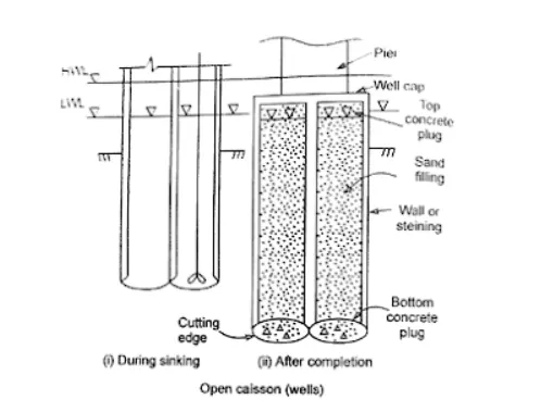
Caissons are usually prefabricated above the ground level and above the water level and sunk to the bearing level as one single unit.
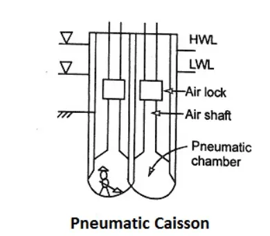
Types of Caissons:-
Box Caisson:-A Caisson which is closed at the bottom but can be open or closed at top.
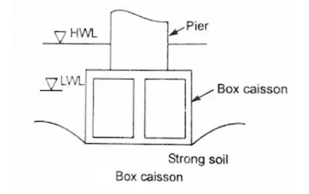
Open Caisson or Well:-A Caisson which is open at the bottom as well as at top.
Pneumatic Caisson:-An open caisson with a chamber at the bottom for maintaining high air pressure.
Forces acting on well foundation:-
Vertical Forces:-
- Self-weight
- Buoyancy
- A dead load of the superstructure
- A dead load of bearing and piers
- Live load transferred through the piers
Horizontal Forces:-
- Braking and a tractive effort of the moving vehicle
- Force on account of the resistance of the bearing against movement due to change in temperature.
- Force due to flowing water.
- Wind pressure.
- Seismic force
- Earth Pressure
Load applied from structure to the foundation.
Bearing capacity of soil.
Depth of water level below the ground surface.
Types of soil and depth of layers in case of layered soil.
Depth of adjacent founadtion.
free standing length in a pile system:-
Piles are mostly installed in groups, it can be divided into two main types based on the connectivity of the pile cap with the underlying soil; freestanding groups, in which the pile cap is not in contact with underlying soil and piled foundations, in which the cap is in contact with the underlying soil.
The surface area of the pile in socket length is calculated by multiplying the socketing length(length of the pile in the fresh rock) by the perimeter length of the pile.
failures in deep foundations:-
Unequal settlement of the sub-soil.
Horizontal movement of the soil adjoining the structure.
Tilt and tolerance failure.
Lateral pressure tending to over-turn the structure.
Lateral escape of the soil below the foundation.
R.C.C failure
Construction Parameters:-
Protective works (Coffer dam, sheet pilling ) to be done around the foundation.
Site clearance and boring shall be done as per indian standards.
Lowering the steel cage after clearing.
Casting the pile by pouring wet concrete.
Bottom plug,sinking and top plugging in case of well.