Week 7 Challenge
DESIGN OF SLIDER FOR CAR DOOR BEZEL:
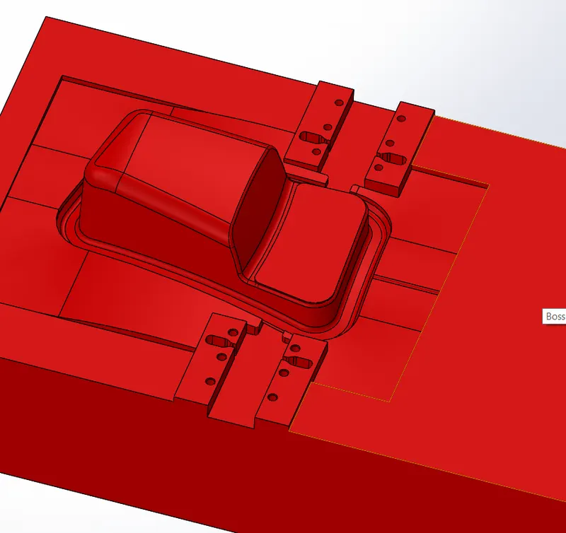
In the previous challenge I have designed the core and the cavity for the car door bezel.In this challenge I had done the slider mechanism for the same car door bezel by using the same core and cavity block which I was created in the previous challenge.
WHAT IS SLIDER?
Due to the special requirements of a product, the mold release direction of a particular part may not be consistent with the mold opening direction of the injection molding machine (product undercut), the slider,also known as slide,is a mold mechanism that is developed to solve the issues with the undercut.
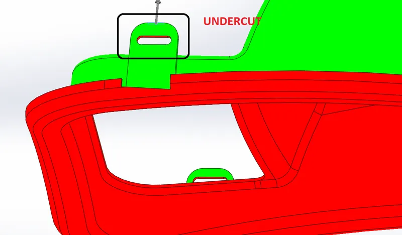
PARTS OF CAR DOOR BEZEL MOULD:
- CORE
- CAVITY
- SLIDER
- WASHER
TOOLS USED :
- CONVERT ENTITIES
- SKETCH
- REFERENCE PLANE
- SPLIT
- EXTRUDED BOSS/BASE
- EXTRUDED CUT
- COPY/ MOVE BODIES
- DELETE/KEEP BODIES
- MOVE FACE
- COMBINE
- FILLET
REFERENCE PLANE:
Tis command is used to create plane or axsis.The reference plane is created perpendicular to the line of undercut region.
SKETCH:
Sketch command is used to create any sketch . Sketch is created on the reference plane created.
CONVERT ENTITIES:
It is a tool available in sketching workbech which is ues to project the sketch selected on the plane you are sketching and in the tool another option of intersection curve is there which is also used to project sketch.
SPLIT:
It is available in features tab used to split the bodies into two pieces along the sketch based on applications.
EXTRUDED CUT:
It is available in features tab used to remove material from a solid body along the sketch in which direction we need based on application.In this design the length of the slider is too long to reduce the length of the slider we use extrude cut option to remove the material.The length of the slider must be 40mm.
EXTRUDED BASE:
It is availabe in features tab used to add material from a solid body along the sketch in which direction we need based on application.In this design we add material to the slider so that the slider can be cut at particular dimention for fixing the slider with bolts and washer.
FILLET:
It is used to make fillets on edges of solid bodies.We give fillet for slider and the cavity block.
MOVE/COPY BODIES:
It is availabe in directing editing tab used to copy or move bodies.In this design we copied the slider block and saved as parasolid format.
COMBINE:
It is availabe in direct editing tab used to add or subract the bodies.In this design I used the copied slider as body to subract and cavity block as main body, and click ok.Now the copied slider body is subracted from the main cavity block leaving the shape of the slider in the cavity block.
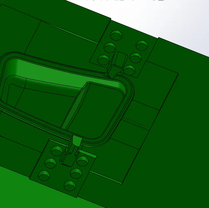
DELETE/KEEP BODY:
It is availabe in mold tools tab to keep or delete a solid or surface bodies.In this design we gonna delete the slider block because we don't need it on the cavity block .It must add as a seperate part in assembly.
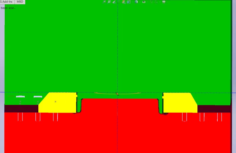
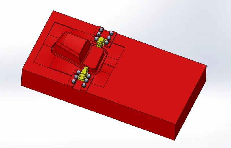
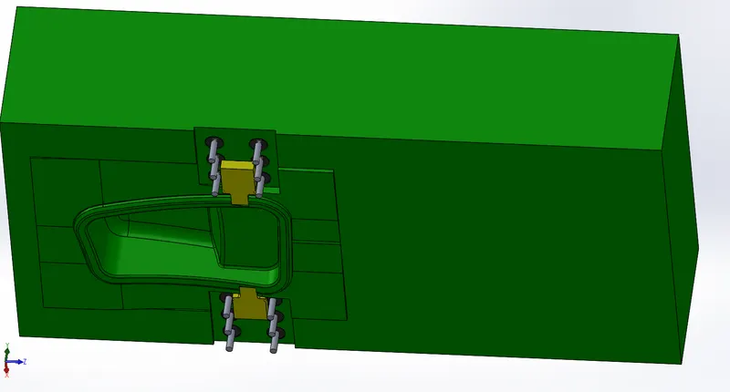
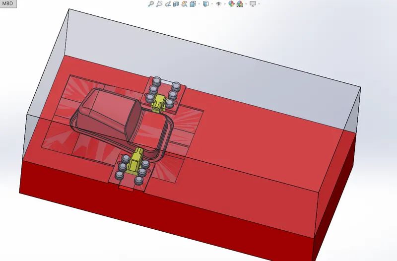
In assembly seperate part file is added and it named as SLIDER_01 because we gonna create 2 slider blocks for both the slides of the molds.Then the slider part which is saved as parasolid is imported to the slider part in the assembly.Add color to the slider as yellow.
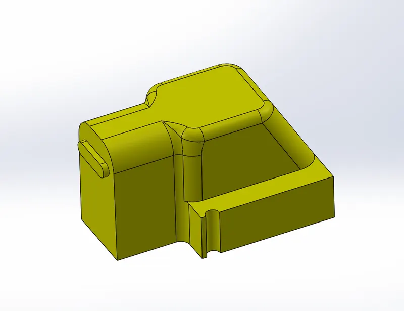
Now accroding to the shape of the slider the core block should edited .For that activate the core part and import the slider .The same procedure is followed as we followed for cavity block.Use combine option and subract the imported slider to the core block.
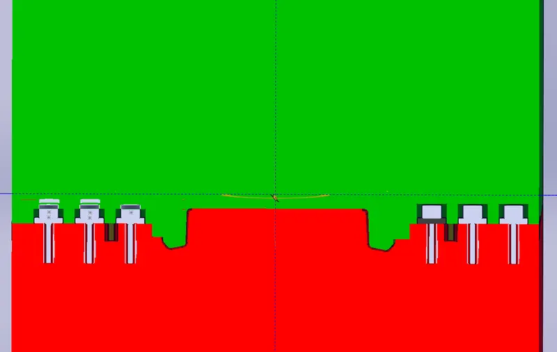
To add the washers we should create a sketch and extrude it on the core side and remove the intersecting parts on the cavity side accroding to the core block.
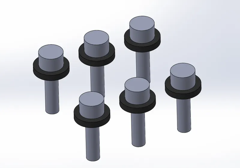
ADD sepertate part file in the assembly and named as washers.Create a sketch and design the washers.The washers are comes in standard we can also imported it from the catalogue browser.
Due to addition of washer there will be a intersection on the both core and cavity blocks.We should remove the intersection materials .
LOCKING MECHANISM:
As the slider movement should restricted , we should create a locking mechanism such that upto some distance only the slider can move for this certain space should be allocated in the cavity block that space is designed considering the distance of travel of slider.
CROSS SECTION VIEW:
MOLD DESIGN IMAGES:
CONCLUSION:
Thus as per the objective the mold design for car door bezel is created along with core, cavity, slider and washer.