Week 7- Base Unit Design Challenges 2
BASE UNIT DESIGN
Base Unit
A base unit is the unit designed to mount all the other units (Clamp unit, Pin unit, rest unit etc.) of the tool, also other parts necessary for a tool like pneumatic valve box, trunking cable path will also be mounted on to a base unit.
The Base unit comes in different ranges and sizes, based on the type of loading it supports for the other units that has been placed on the base unit.
Different Panel and surface parts have different dimensions and its own criticality. The Base unit should be designed in such a way that, the operations performed on the panel are done smoothly, without having the adverse effects on the neighboring tools and units.
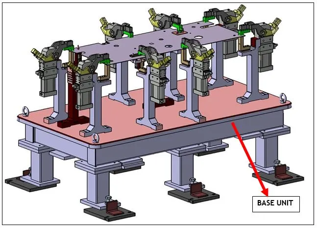
Major parts of Base unit
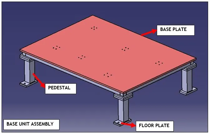
The major parts of Base Unit are as follows:-
1) Base Plate.
2) Pedestal.
4) Valve Box.
5) Eye Bolt.
6) Floor Plate.
Ø Base Plate
Base Plate is a machined plate of 25 to 40 mm thickness made of steel and aluminium, on to which the holes are drilled to mount the individual units like clamp unit, pin unit etc., of a tool.
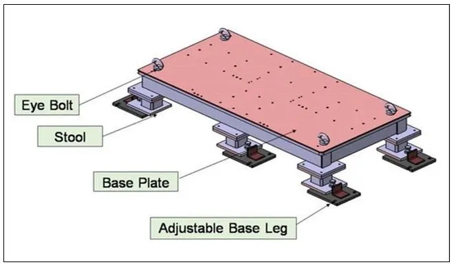
The Base plate is designed as per the requirement and specification called by the client. Based on the complexity of the panel / surface part on which the operations are performed, there are different types of attachments available to perform flexible tasks.
Ø Pedestal
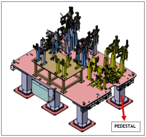
A pedestal is a part which connects the base plate to the floor plate. A pedestal is a standard part in general and in some cases, it can be a welded frame integrated with the base plate.
FEATURES OF PEDESTAL
· A standard pedestal can be of different height and different size.
· Depends on the size of the base plate, the number of pedestals varies for load distributed.
· Pedestal are available in different types with different inclination.
Ø Trunking Channel
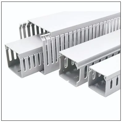
A trunking channel is a duct which accommodates all the pneumatic and electrical hoses and wires for the units of the tool.
The trunking channel makes that, all the cabling and wirings are grouped and laid under the channel, in order to make the base unit free, so that any operating tool performing operation on the panel, doesn’t make contact with the cablings.
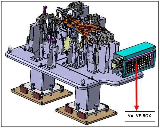
Ø Valve Box
Valve box is standard part which accommodates the pneumatic valves for the units.
A pneumatic actuator comprises of Air-Filter-regulator set, Flow control valves / Directional control valves & solenoid valves for actuating the pneumatic cylinder.
Ø Eye Bolt
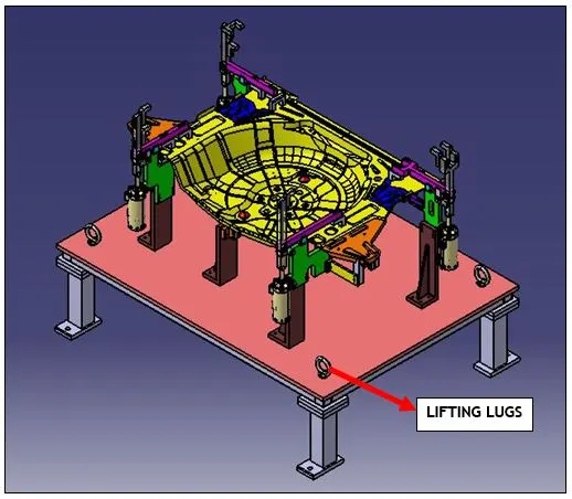
Eye bolts are the only bolts, which helps to lift the base unit for shifting purpose.
The eye bolts are on the corner of the base units. The hook of the lifting crane links to the eye of the bolt to make a locking mechanism, so that when the base unit is lifted and in motion from one place to other, the slipping of the base unit should not occur.
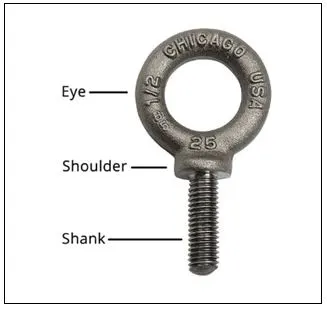
When lifting the base unit, it is common for an eyebolt to be screwed directly into a tapped hole in the structure. In this case, an eyebolt is required that is fully threaded all the way up to the shoulder. When an eyebolt is intended to be inserted through a hole and fastened by a nut on the other side, it is better if there is a shank. A shank is an unthreaded section of the shaft, below the shoulder, which provides a better transfer of load into the surface of the hole and is less likely to crack under a fatigue loading.
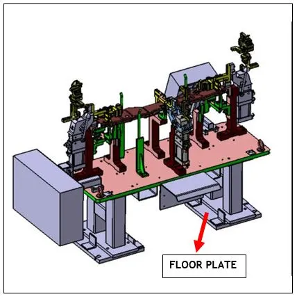
Ø Floor Plate
Floor plate is grouted to the floor with fixed bolt on the ground. Floor plates are also called as foundation plates.
· There is a clearance of 10mm maintained between the pedestal base plate and the floor plate.
· This clearance will be used by the levelling screws for levelling the entire tool.
· Weld bars are to be weld to the positions permanently after levelling is done.
· A weld bar is a plate along the sides of the base plate of the pedestal.
POINTS TO BE CONSIDERED FOR DESIGNING A BASE UNIT
The important parameters that are need to considered while designing the base unit are as follows: -
Ø Working Height: -
Working height depends on the nature of the welding fixture. It may be manual or robotic welding fixture.
For manual fixture, we have to consider the working height between 850-1100 mm, depending upon the height of the worker, who is performing the necessary operation. Different countries have their own pre-defined height standards.
If the base structure is made with a base plate having tubular structure welded below it we can reach to height 100 mm to ~250 mm. In this case to reach the working welding height, we need to provide additional leg support structure which will help in top structure and plate weldment to the tube.
For a designer it is important to know that how big base plate or bigger base welded structure will be handled during the fabrication and handling process. Special care needs to be taken care of flatness if the base size is very long.
Depending upon the weight, the eyebolt size are selected for lifting holes on the base plate. Generally, provision of 4 / 5 / 6 eye bolt are made, based on the magnitude of job done. This eye-bolt helps in lifting the base plate from one place to the other place for movement purpose.
Ø Base plate or welded structure
The base plate can be fabricated by using welding technology on ready-made plates or we can use the readily available standard tubes in round or square shape to fabricate the base plate.
Ø The Manufacturer makes 4 dowel holes at 4 corners and puts small aluminum plate marking X, Y & Z coordinates of dowel holes.
Ø The base unit of the fixture must be strong enough so that deflection of the fixture is as minimum as possible. This deflection of a fixture is caused because of forces of welding, clamping of the workpiece.
Ø The base unit may be built from simple sections so that other units may be fastened with screws or welded whenever necessary. Those parts of the fixture that remain permanently with the fixture may be welded. Those parts that need frequent changing may be held with the screws.
Ø The base unit should cover all the units with its outer periphery including the opening.
Ø The base unit should be parallel to the floor. To make necessary adjustments there should be the provision of height adjusting mechanism. The designing of Swivel Clamp unit is similar to that of a clamp unit. But, one change in the swivel clamp unit is that, the clamp arm is actuated by using the linear acting power cylinder.
DESIGNING OF BASE UNIT USING CATIA
In CATIA, The Base unit is designed and modelled with all its sub-assembly parts meeting the design criteria, explained above.
The BASE UNIT is designed for the swivel clamp unit and fixed unit assembly, which were modelled in the last challenge (Base unit Design Challenge-1)
Newly rest units are added to make the BIW panel comply to the six degrees of freedom and its conditions.
The final
assembled view of the BASE UNIT is shown in the below diagrams: -
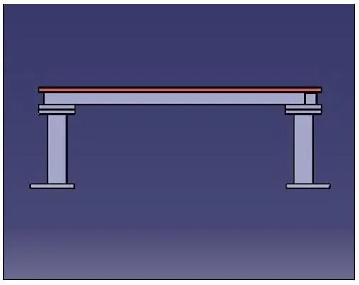
Ø UPSIDE DOWN VIEW OF THE BASE UNIT
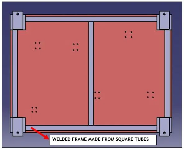
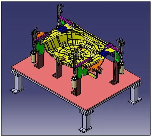
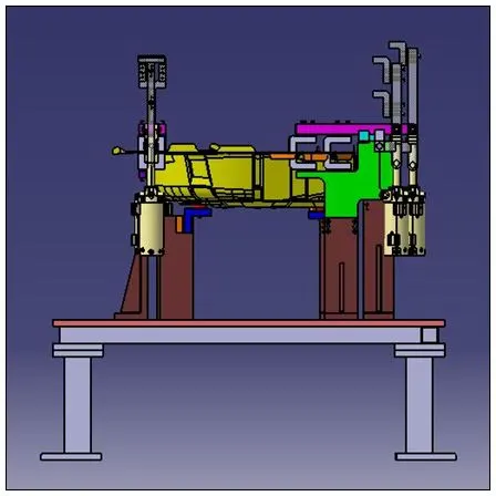
The Swivel clamp units / Rest units / Fixed Units are bolted on the base plate of the BASE UNIT.
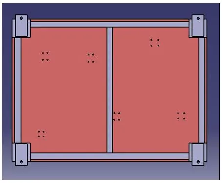
The square tubes which are used as the support structure for the base plate are placed in such a manner that the load from the Swivel clamp units / Rest units / Fixed Units are distributed across the base plate in a uniform manner.
The arrangement of the square tubes, once decided is then welded to form a WELD FRAME, as shown in the above diagram.
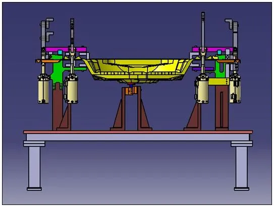
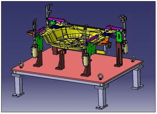
The base unit along with Swivel clamp units / Rest units / Fixed Units are shown below
COMPLYING TO DESIGN CONDITIONS OF BASE UNIT
The BASE UNIT is designed complying to the minimum conditions which fulfils its construction.
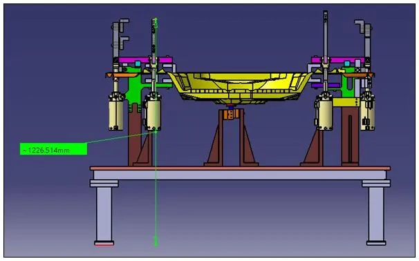
1st CONDITION: - The distance starting from the point of clamp arm in de-clamped position to the ground where the pedestal of the base unit rests, should be 1200 MM or more.
The base unit modelled fulfilling the 1st condition is shown in below diagram:-
2nd CONDITION: - There should be one support tube present in the middle of the base plate of weld frame, to prevent from deformation and balancing the load distribution coming from the units resting on it.
The base unit modelled fulfilling the 2nd condition is shown in below diagram:-
FINAL ASSEMBLED VIEW OF BASE UNIT
File Path to view the BASE UNIT ASSEMBLY
Ø Open Folder – ‘Week-7 - Base Unit Design Challenge-2_Somashekar B’ ----> Open Folder – ‘Base Unit_Assy_S’ ----> Open the file named – “P001_Z01_ST01_SWIVEL CLAMP UNIT ASSY_S.CATProduct”