Week 7- Base Unit Design Challenges 2
AIM:
To design a base unit for the pin unit and clamp unit including swivel clamp unit with all weldments for the given car panel.
2.Design all the other remaining unit required for this fixture assembly.
THEORITCAL PROCEDURE:
BASE UNIT:
A base unit is the dsigned to mount all other unit (clamp unit , pin unit , rest unit etc) of tool ,also other parts necessary for a tool like pneumatic valve box , trunking cable path will also be mounted on to a base unit , and below are the same parts of base unit in genral.
They are trnking channel , base plate valve box , measring hole cover eye bolt , pedestal , weld bars and floor plate.
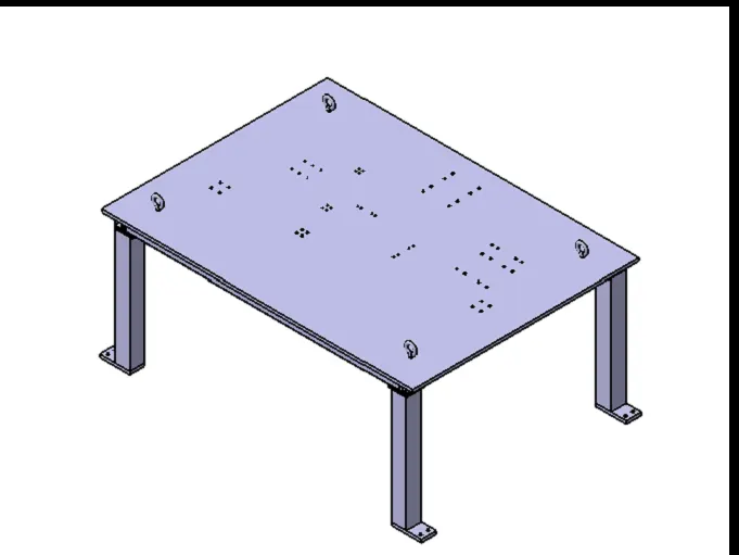
TYPICAL PARTS OF BASE UNIT:
BASE PLATE:
The base plate is a plate of 20mm to 40mm thickness .
The base plate has no. of hole on it which will act as mounting points for clamp unit , pin unit etc . of a tool.
PEDESTAL:
It is used to connect the base plate with a floor plate
the pedestal can be a standard part or a make part , depending on the size and height of the fixture.
standard pedestal are available of the fixture .
Pedestals are also available in different inclinations.
Depending on the size of the base plate , the number of pedestal for a fixture can vary for load distribution.
TRUNKING CHANNEL:
Trunking channel is a duct that carries all the electrical and pneumatic connections (wires and pipes)for unit of the tool.
VALVE BOX:
Valve box is a standard part which will accommodates all the pneumatic valve for the unit . the valve box is the box which includes all the pressure inlet cable going to pneumatic parts of the fixture & protects them from damaging while operation process.
EYE BOLT :
Eye bolt are bolts that are used to lift fixture for transportation by inserting hooks into them.
for example , usually we use M20 bolts that are bolted on the base plate .
used for transportation purpose , sometimes forklift will be provided .
FLOOR PLATE :
floor plate is grounded to the floor with bolt on the ground
floor plate are also called as foundation plate .
There will be a clearance of 10mm maintained between the pedestal base plate and the floor plate.
This clearance will be used by the leveling the enitre tool .
Weld bars are used to weld the position permanently , after leveling is done.
A weld bar is a plate along the sides of the plate of the pedestal
BASE NEEDS TO DESIGN A BASE UNIT:
1.Working height :
it depends on the nature to the manual robotic welding fixture.
- For manual fixture we need to consider the working height 850-1100mm, depending upon the working height of the worker standard of a specific country will apply.
- If base structure is made with plate having tubular structure welded below it . we can reach to height 100mm to 250mm . in this case to reach leg structure which may have tap&plate welded to the tube .
- As designer it is important to know how big base plate or bigger base welded structure will be handled process . special case needs to take care of flatness if the base size is very long.
- Depending upon the weight eye bolt size selected for lifting holes on base plate . generally 4 eye bolt provision is made . You also need to select the loaction of eye bolt considering the rope/ belts used while shifting the structure or complete fixture are not damaging any unit nearby.
- Most of the OEM makes 4 dowels holes & put small aluminum plate plates marking x,y,z coordinates of dowels holes . if the base length is too longs few OEM's follows the methodology of having holes at 500mm distance .
- The base unit of the fixutre must be strong enough so that deflection of caused becouse of force of welding , clamping of the workpiece.
- The base unit of built from simple section so that other unit may be fastened with screws or welded necessary . Those parts of the fixture that remain permanently with the fixture may be held with screws.
- The base unit should be parallel to the floor ,to adjust this should be provision of the height adjusting mechanism.
FUNDAMENTAL OF BASE UNIT :
- A base plate size should cover all units with its outer pelates is always preferred to be designed with respect to BCS cordinated.
- A base plates should be drilled with datum holes / measuring holes in line with a pitch of 1000m in general.
- Number of datum holes is depends on the size of the base plate.
- datum holes should be coverted with cover plates
PRACTICAL PROCEDURE:
- We have to consider welding gun to designing a base unit.Because the welding gun has to flow through between panel and base plate. So first we have to measure the height between panel and base plate.
- The minimum space between the welding gun and base plate is 50 mm to 100 mm. because this is why we are creating the fixture.
- The base plate have to be strong and rigid to hold the entire fixture tool for welding process.
- In some cases the base unit is mounted on a tolley or it will fix to a slide bases unit.
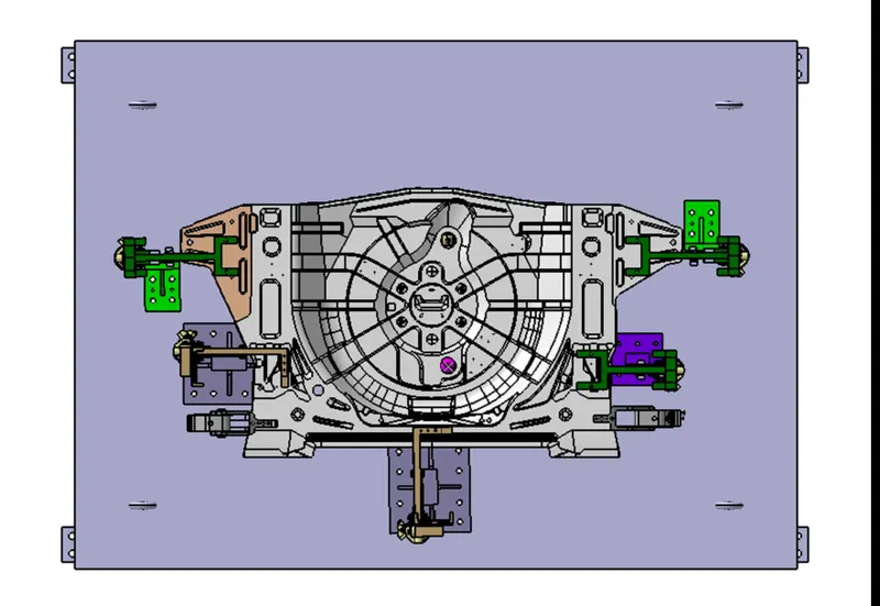
FIG. TOP VIEW
The base plate has diferent types of weldments and it varies when it comes from the customer.
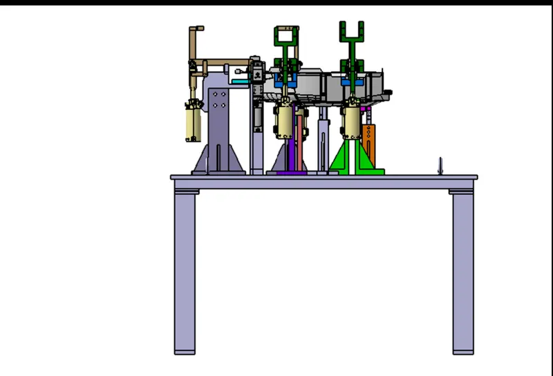
FIG LEFT SIDE VIEW
The base unit must be very strong enough so that deflection of the fixture is minimum as possible. This deflection is caused because of forces of welding , clamping of the work piece.
In this project the base plate thickness is 20mm which is machined to maintained the parallelity which is very useful to when to mount the unit.
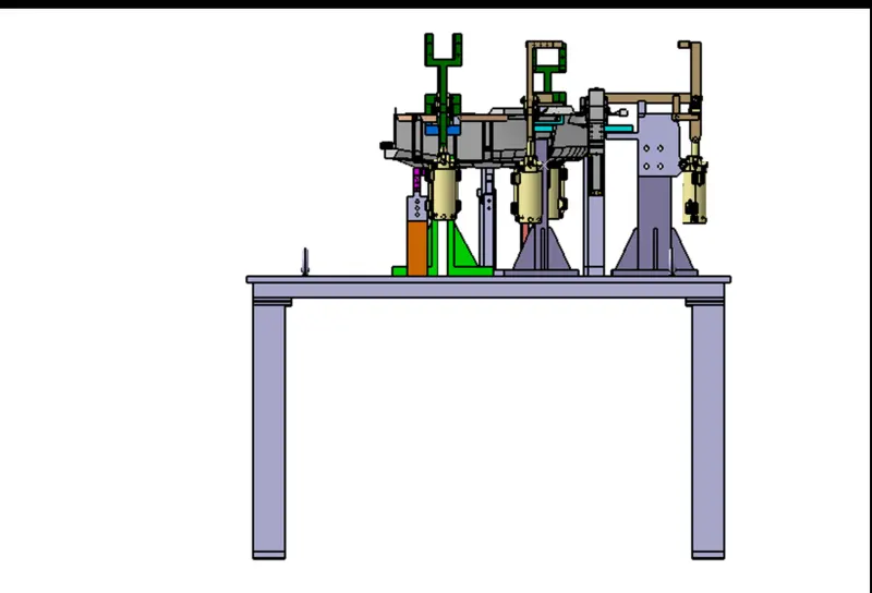
FIG. RIGHT SIDE
The base unit should have the mass to prevent vibration and chatter.
The permanent parts like weldments has to be very strong enough to hold the all units and so do validity of the base unit will long.
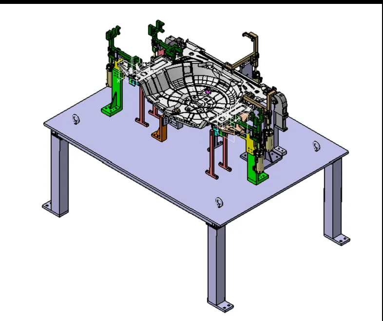
FIG. ISO VIEW OF WHOLE TOOL
The base unit should cover all the units with its outer periphery including opening positions.
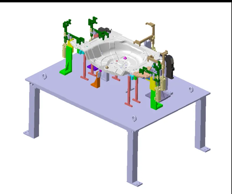
FIG. RENDER VIEW
The most important thing is once when we create the whole tool. the design have to move on to next stage to simulation. this process is also called as tool validation.
This bolt is used to adjust the height of the base unit. The base unit should be parallel to the floor, to adjust the provision of height adjusting method. Here in this design we can adjust the height upto 10mm in upwards & downwards direction.
In this project i have done the design to follow 3-2-1 principles. it is necessary to restrict all the degrees of freedom to weld the panel.
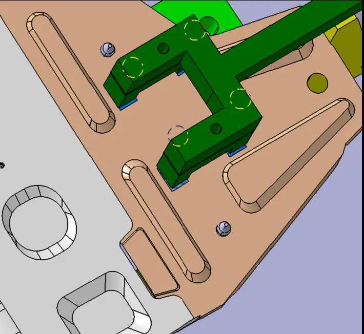
In this project the blue and orange panels are very small when consider to the yellow panel. i have created seperate units for pin unit. if we cannot achieve all the weld spots. we can unclamp some units to achieve those weld spots.
In this project the clamping positions are so near to the other units. So in standard we cannot achieve a weld spot it will be moved to re-spot station. But here the panel is too big. so the robots are not capable to operate this panel to achieve the weld spot.
For that we can unclamp some units to achieve those weld spots.
CONCLUSION:
Here as per the objective to design a base unit for the pin units and clamp units including swivel clamp unit with all weldments for the given car panel has been designed with 3-2-1 principle.