Week 7- Base Unit Design Challenges 2
Base Unit and Fixture Unit
Aim: To design base unit for a fixture unit.
Base Unit Introduction:
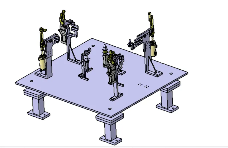
Base unit holds all other units and tools necessary for a fixture assembly. Units like pin unit, clamp unit, etc. are loaded on the base unit. The individual parts of the base unit are welded together. The base unit is designed depending on the requirement of the fixtures.
- Working Height:
- The working height of the component needs to be around the height of 900-1100. This height is determined by the average.
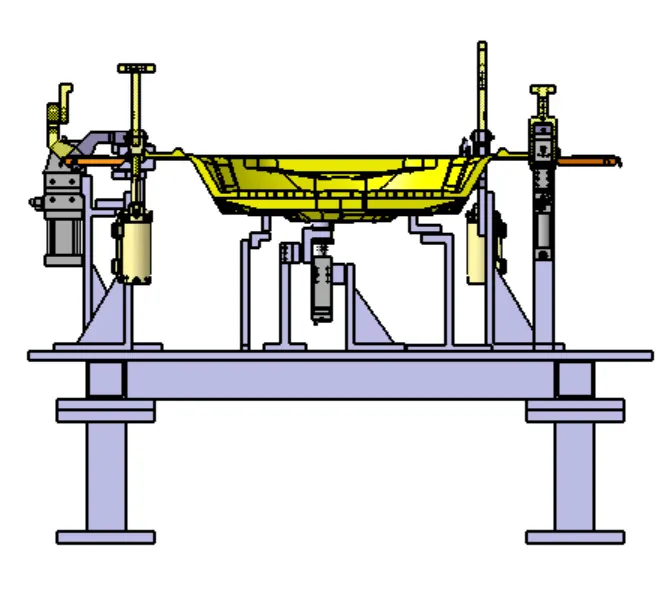
- The height is provided by adding pedestals under the base plate. The height of these pedestals depends on the cylinders used of the equipment used for the particular unit.
- Base Plate
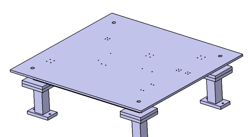
- The base plate should cover all the units mounted on it as well as the opening positions of the units.
- The datum holes need to be of 1000mm pitch. The number of holes depends on how big the base plate is.
- The hole coordinates need to be in multiple of 50 for easy manufacturing.
- The holes should be at least 100mm away from all the units.
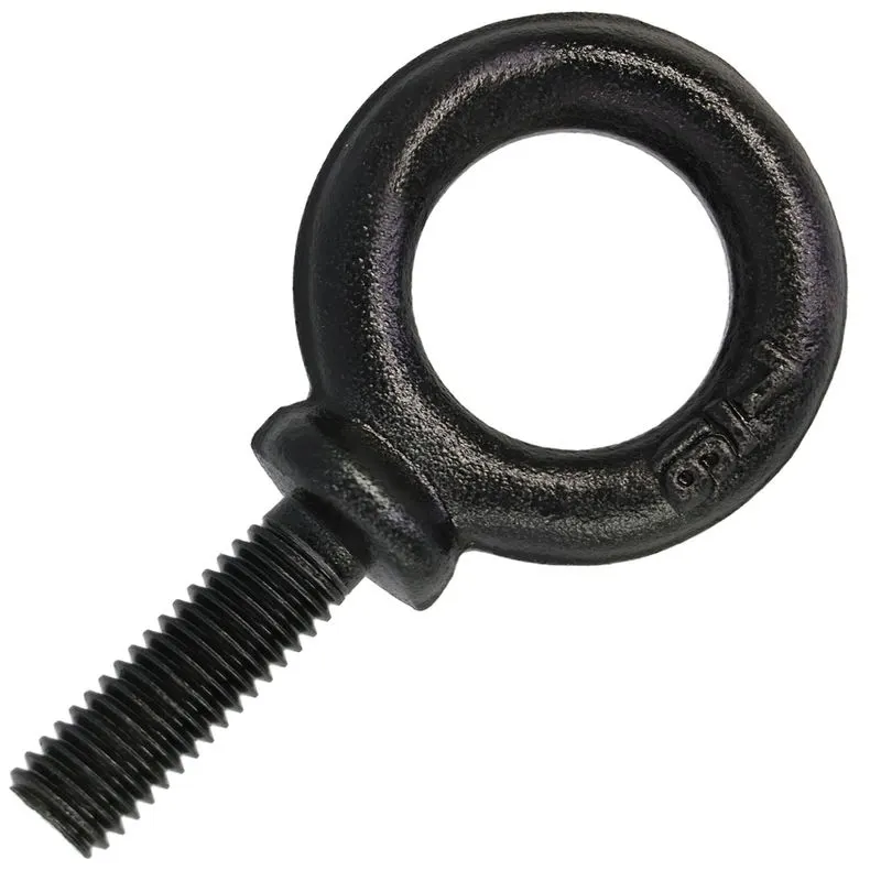
- Eye Bolt: Generally, 4 eye bolts are provided for lifting of the assembly. Then location of these bolts is selected such that it does not harm or damage the units placed on the base plate.
- The base unit should be strong enough to resist the deflecting forces caused due to various operation on the unit.
- The base unit should be stable enough to cancel out the vibrations.
- Parts that need frequent inspections should be bolted or screwed together and parts that need not be changed again can be welded.
- The entire unit needs to be parallel to the floor and needs to have allowance for adjustment.
Parts of the Base unit:
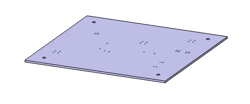
Base Plate:
It is usually made of aluminum or steel with thickness ranging from 25mm to 40mm. Holes are provided by drilling for mounting for different units that are required to be mounted.
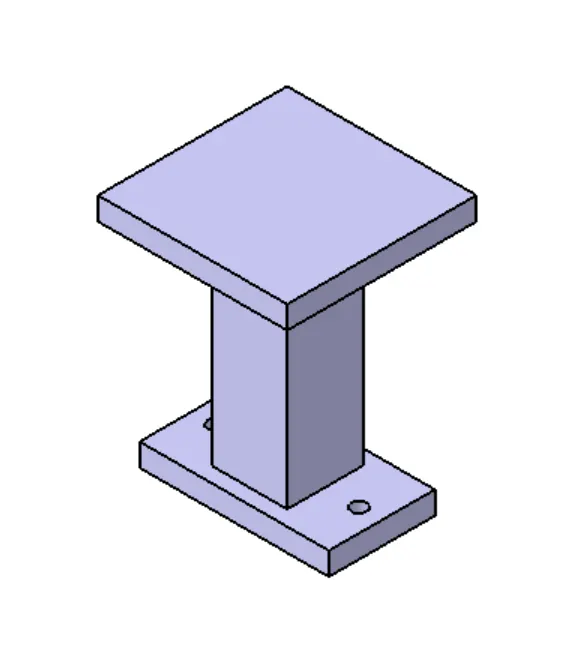
Pedestal:
It is a standard part and is welded together with the base plate, it connects the base plate to the floorplate. The number of pedestals required is depended on the load carried by it. The height and size defer w.r.t the same. The height of the pedestal is decided such that the working surface comes to a height of 900-1100mm. This height is needed for ergonomic purpose, as the operator needs to operate at a safe height which can cause less fatigue.
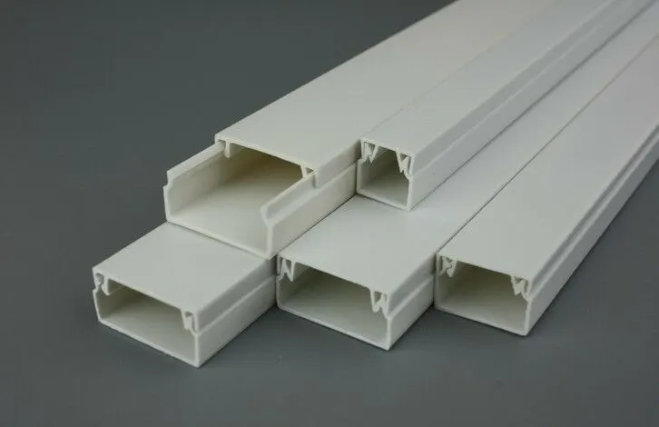
Trunking Channel:
It is used to guide the wires and cables required in the assembly. It helps with improving the aesthetics of the assembly as well as organize it in a way which is easy to understand at the time of inspection. It also protects the wires from other possible damages whiles different operations are done.
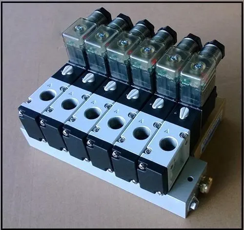
Valve Box:
It accommodates all the pneumatic valves for the unit. The valve consists of different solenoid valves. The pressure for operating different cylinders is controlled through the valve box. The cables needed is connected through the trunking channel.
Eye Bolts:
While transferring the unit from one area to another, it needs to be lifted with the help of different equipment. Hence, for lifting purpose, an eye bolt is provided in the unit where hooks can be attached for easy lifting of the unit.
Floor Plate:
Also know as foundation plates, these are bolted to the ground. There is a clearance of 10mm maintained for leveling. Once it is done, weld bars are used to permanently weld the part.
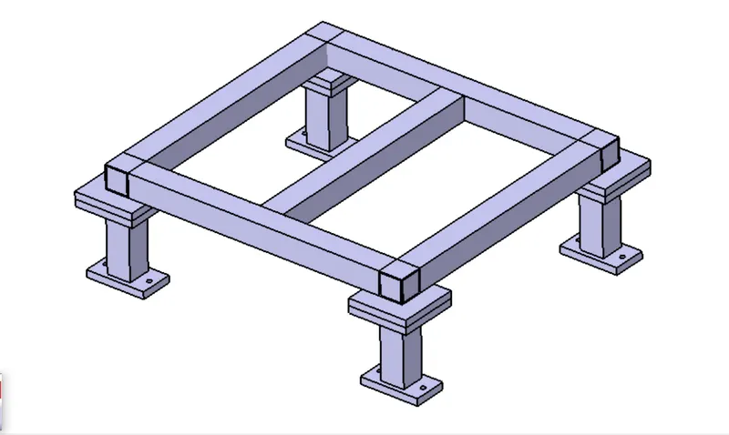
Square tube and pedestal for support and providing height to the unit.
Fixture unit.
To lock all 6 degrees of freedom. Various units are used.
There are total 6 degrees of freedom. in order to lock 3 degrees of freedom, the components need to rest on something. Next, to further lock 2 degrees of freedom, the sliding moment needs to be constrained. To keep different components from moving, they need to be clamped together in order to arrest it's movement.
Hence, for the above mentioned units, following units are designed.
For locking first degrees of freedom, i.e.,
1. Up and down movement of the component.
2. Rotation about x axis. (Assuming the flat ground to be parallel to x axis; and y axis to be perpendicular to x axis and parallel to ground.)
3. Rotation about y axis.
In order to arrest these motion we use rest unit.
1) Rest Unit:
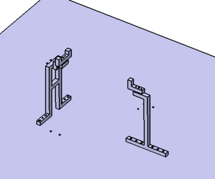
- It is the simplest unit to design and has the minimum number of parts.
- It is used to rest the component.
- No clamping finger is used. There is no force applied from above to hold the panel.
- It is usually added with other units to reduce cost of production.
- It is combined with either locating unit or all three are put together.
Parts of the rest unit are:
Resting Mylar: It is the part which is directly in contact with the workpiece. The car panel rests on the resting mylar, just restricting it’s up and down motion.
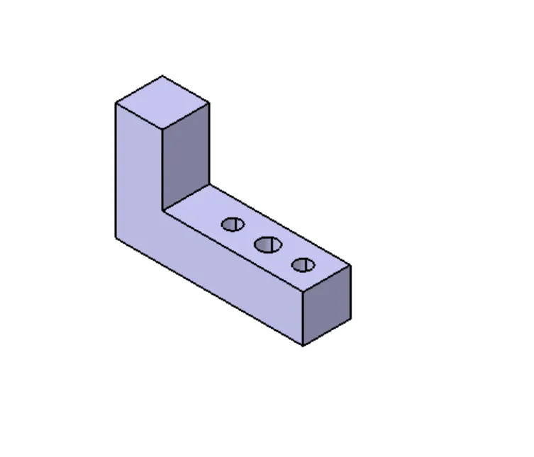
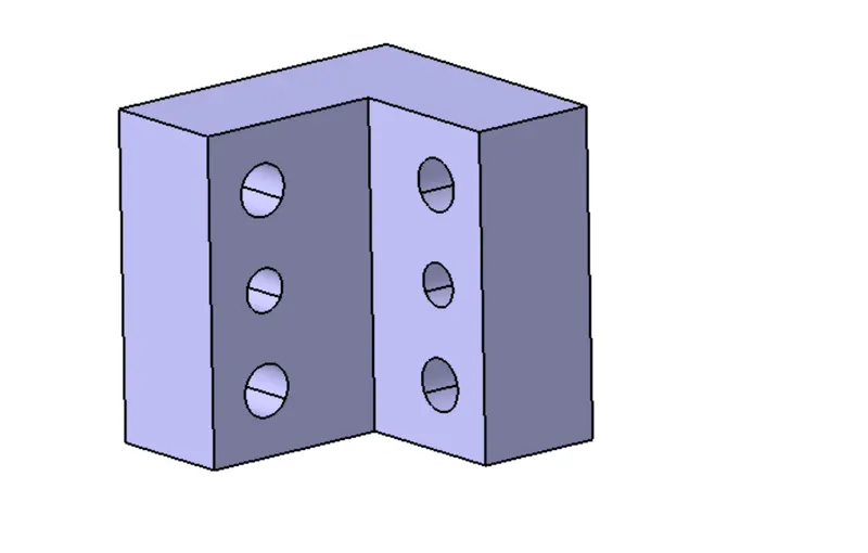
L-block: When the mylar needs to be adjusted in two directions, a blade can be added to the assembly. Or when there is space restrictions, L-block can be used.
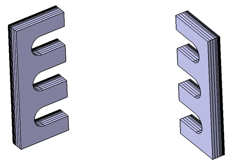
Shims: It is used to manage the stack up tolerances and a pack of shims having an overall thickness of 5mm is used.
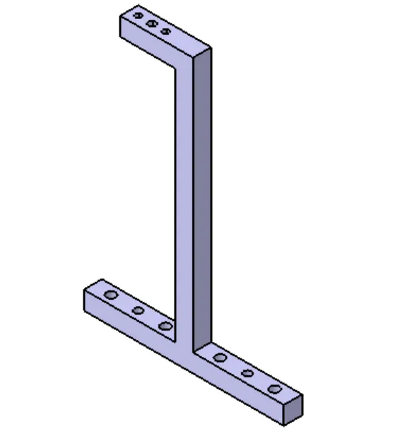
Riser: It is the resting part which is attached to the base and supports all other parts on it.
Using the above rest unit we can constrain 3 degrees of freedom.
Next, we need to constrain sliding movements, and rotation about z axis.
for this we need to design pin unit. it can either be retratable or fixed.
Pin unit will constrain the following degrees of freedom.
1. Forward and backward moment.
2. Side-to-side moment.
3. Rotation about z axis ( for this we need more then one pin unit.)
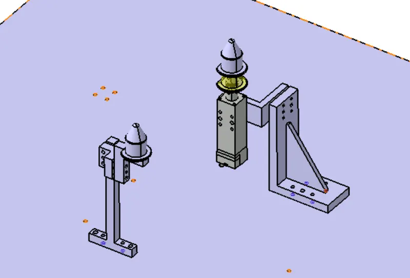
Pin unit:
A pin unit generally consists of pin, retainer, block, riser, spacer and shims along with bought out parts like cylinders for retractable pins, bolts for fastening of the parts together in the assembly.
A pin unit is used to locate the parts that need to be worked on and is part of the 3-2-1 locking principal.
Fundamentals of pin unit design:
- Pin should engage at 3mm to 5mm from the car panel.
- Adjustable shims should be provided such that they can adjust the position in two ways.
- Round pin should stop 4 degrees of movement if it is a hole.
- Round pin should stop 2 degrees of movement if it is a slot.
- Diamond pin should stop 4 degrees of movement if it is a slot.
- Diamond pin should stop 2 degrees of movement if it is a hole.
Parts of the Pin Unit:
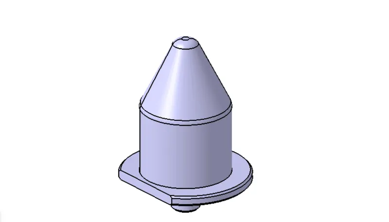
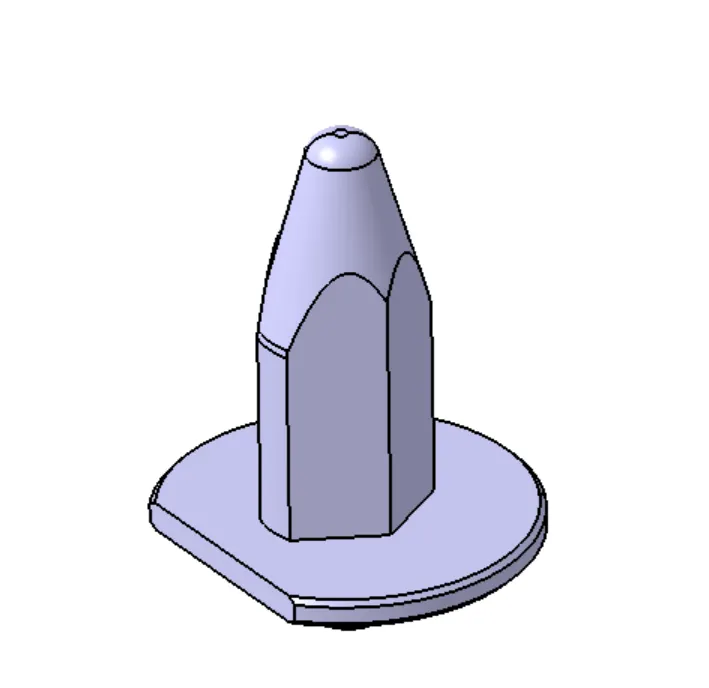
Pins:
- There are two types of pins, round and diamond pin.
- It is the part of the unit with directly comes in contact with the panel.
- It is used to locate the panel.
- Pins should have a counterbore at the bottom for fastening on the retainer.
- The mounting surface coming should be machined.
- The pin should be perpendicular to the resting surface on the retainer.
Retainers:
- Used to mount the pins and is usually screwed together.
- The pin retainer is fixed to the L-block with the help of 2 dowel pins and 1 screw.
- The surface mating to the pin should be machined.
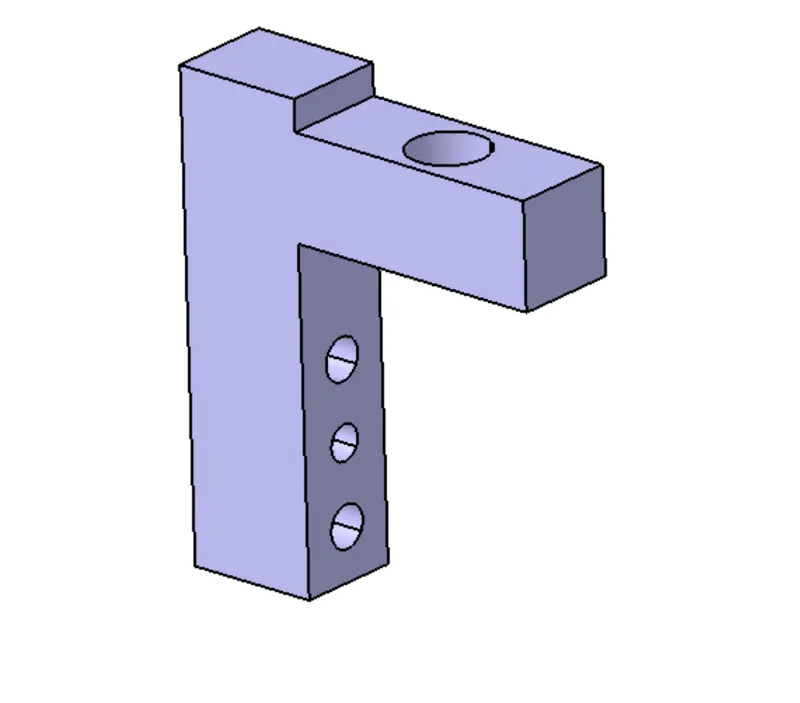
L-Blocks:
- Used for adjusting the pin position in two directions.
- It is fixed to the riser using 2 dowel pin and 1 screw.
Riser:
- It is mounted on the base and is used to support all other parts.
Shims/Spacer:
- It is a batch of machined plates usually 5mm thick, with varying induvial thickness from 1mm, 0.5mm, to 0.25mm.
Cylinders:
- For retractable pin units, cylinders are used.
- There are two types of cylinders, one which is directly attached to the pin.
- Other types which are attached to the L-block in case of space constrains.
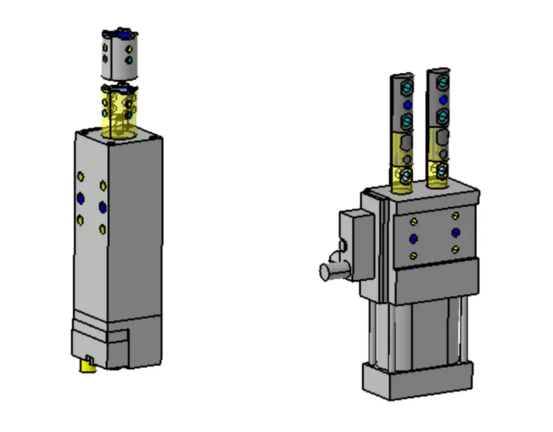
Thus, we constrain the entire panel. by using rest units and pin units, we stop the motion of the panel in all 6 dirctions and hence, the component can be worked upon.
Although, the degrees of freedomare constrained, only one panel can be constrained in this way. In order to work on the panels that need to be attacted together, we use clamp units to clamp the parts together and stop them from moving.
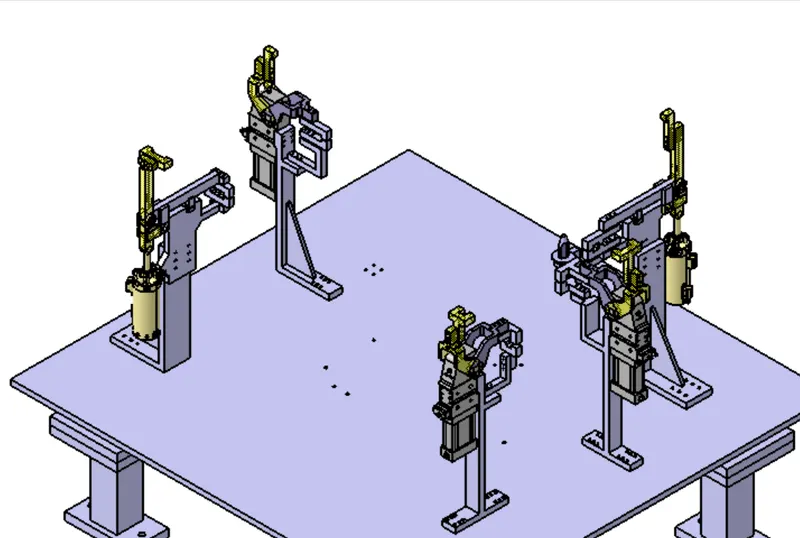
Clamp unit:
Clamp Unit Basics:
- 3-2-1 Principle: This principle is used for locking the 6 degrees of freedom of the component. A resting unit locks 3 degrees of freedom. The up and down movement and 2 rotational degrees of freedom.
- For locking all 6 degrees of freedom, 3 supports are placed to form the first datum.
- Next, we add clamping units to and add minimum of 2 pin units to arrest all 6 degrees of freedom.
- Forces on Clamp Units: Clamping force: It is the gripping forces acted on the panel due to the gripping of the clamping mylar. Holding Force: it is the maximum force by the resting mylar after locking it into position. It is an important factor and if the force level is exceeded then it can cause distortions in the components after procedures like welding are carried on it.
Factors to consider while designing clamp unit:
- There should be enough space between the cylinder and other parts for free and correct movement of the calm arms.
- The contact area for stopper-clamp arm and the cylinder-clamp arm should be finished surface for smooth motioning.
- All parts should snap at correct positions.
- All clamp unit parts should be at least at a distance of 10mm in order to not damage the panel.
- Clamps should be made such that it can clamp 2 panels at once.
Clamp Plan:
- Clamp plan is provided by the customer and should not be modified without their knowledge.
- It mentions the cad data and the parts and placements of the units along with tolerances.
- In case of changes, the modified positions need to be approved the customers before implementation.
Parts of Clamp Unit:
- Resting Mylar: Same as in rest unit, it is used to hold the component in place and the holding force is kept in mind while designing.
- Clamping Mylar: the clamp holds the component from above and is placed directly above it. The clamping force is determined by the outreach of the clamp mylar. It is calculated by calculating the horizontal distance between the center of the finger touching the car panel and the center of the rotating axis of the span arm.
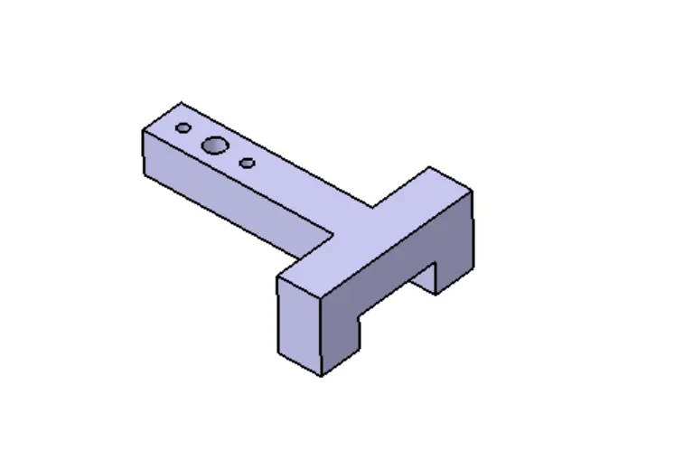
- Blade: Used to attach the resting mylar to the riser. As well as support the cylinder. It has a pivot hole to attach clamp arm. Stopper is mounted on the blade.
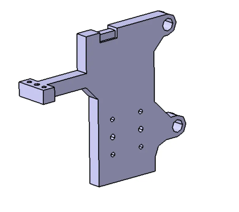
- Stopper: Stopper is used to stop the clamp arm at a position desired. It is mounted on the blade.
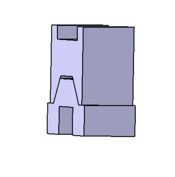
- Clamp Arm: Clamp arm is attached to the clamping mylar and is used to lift the clamping mylar with the help of cylinder. It has a pivot point with the blade.
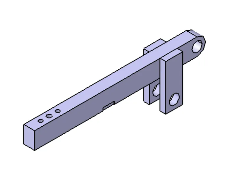
- Shims: Used to compensate for the stack up tolerances and is usually of an overall thickness of 5mm.
- Cylinder: It is a bought-out part and the span arm is attached to the cylinder which is connected to the clamping mylar.
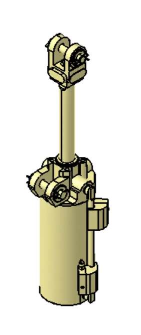
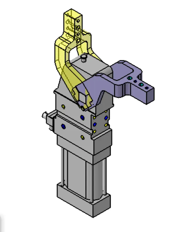
In case of above cylinder, a seprate clamp arm need not be used.
- Riser: Is the attached to the base plate and all the other parts are mounted on it.
Clamp-Pin Unit:
It consists of all the parts mentioned in the clamp unit. In addition, there are following parts to it,
- Pin: It is the locating pin, which can be a round or diamond pic depending on the need. It is used to keep the panel steady, so that is does not move which different process are carried out on the panel.
- L-Block: It is used to provide a two-way shim for adjusting the pin location which might change depending on the stack up tolerances.
- Arm: It is used to connect the pin unit to the clamp unit. One end of arm is attached to L-block and the other end is attached to the blade.
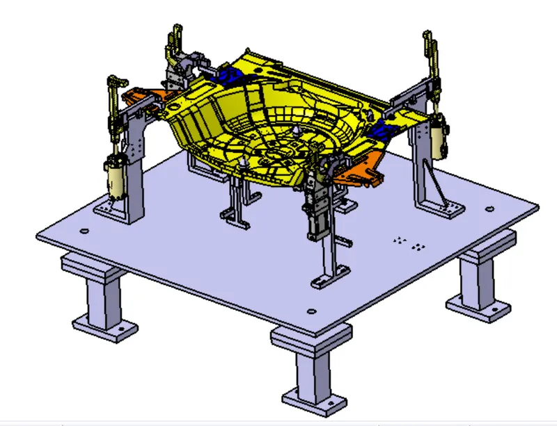
Hence, using all the above mentioned units we can arrest all the components in the desired location. Only after this, the components can be worked on.
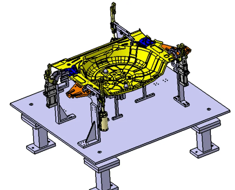
Fixture Assembly:
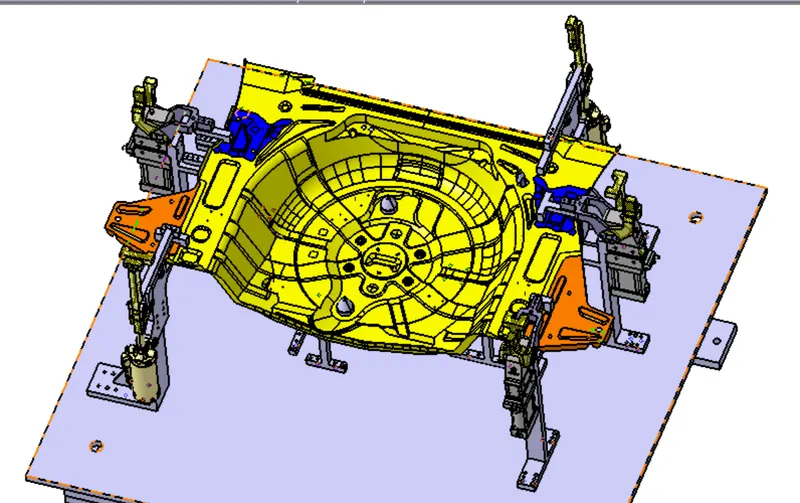
Conclusion: Thus, we designed the base unit for a fixture assembly as well as all the other units needed to complete a fixture unit.