Week 7:- Base Unit Design Challenges 1
1.What is the Base Unit? What are the typical parts of the Base Unit?
The base unit is the unit to mount all the other units like Clamp Unit, PIN unit, Rest Unit, etc. of the tool, also other parts necessary for tools like pneumatic valve Box. The Trunking Cable path will also be mounted onto a base unit.
Typical Parts of the Base Units
1. Base unit
Base unit consists of a base plate is a machined plate of 25mm to 40mm thickness made of steel and aluminum, on to which the holes are drilled to mount the individual units like clamp unit, pin units, etc of a tool. Also, other parts necessary for a tool like a pneumatic valve box, trunking cables patch will be mounted on a base unit. The base unit can also mount components like a valve bank, junction box, eye bolts, trunking cable patch, etc.
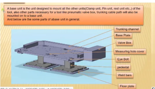
FIG-BASE UNIT
PEDESTAL
A pedestal is a part that connects the base plate to the floor plate. A pedestal is a standard part in general and in some cases, it can be welded frame integrated with the base plate
- A standard pedestal can be of different height and different size
- Depending on the size of the base plate, the number of pedestals varies for load distribution.
- A pedestal is of different types with different inclinations.
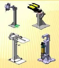
FIG-PEDESTAL
TRUNKING CHANNEL
A Trunking channel is a cloud of dust that accommodates all the pneumatic and electric hoses and wires for the units of the tool.
It has a thickness of a few millimeters
Trunking channels include all the pressure inlet cables going to pneumatic parts of the fixture & protecting them from damage while the operation is in process
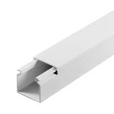
FIG TRUNKING CHANNEL
VALUE BOX
Value box is a standard part that consists of all the values for the pneumatic units. the value box includes different solenoid values the pneumatic fixtures work on air pressure to it. so the arrangement of air pressure inlet & outlet is done within this value box .the trunking channel includes all the pressure inlet cables going to the pneumatic parts of the fixture & protects them from damage while operating is in process.
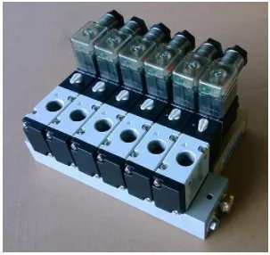
FIG VALUE BOX
MEASURING HOLE COVER
Measuring holes are drilled over the base plate which has exact coordinates and acts as a reference for the other holes .due to irregular shaping of the car panel the coordinates of the holes are not normal like 250,0. 310,0. But it Is like 250,62.310,84.these holes are covered n=by using some plates to protect against dust, damage, etc.
EYEBOLTS
Eyebolts are the bolts that are used to lift the fixture for transportation by inserting hooks into them, for example, we usually use m20 bolted on the base plate .used for transportation purposes some time forklift holes will be provided.
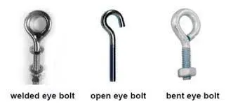
fig-EYE _BOLTS
FLOORPLATE
Floor plates are also known as foundation plates. They are grounded by using a fixed bolt minimum of 10mm clearance should be given between pedestal base plate and floor plate.
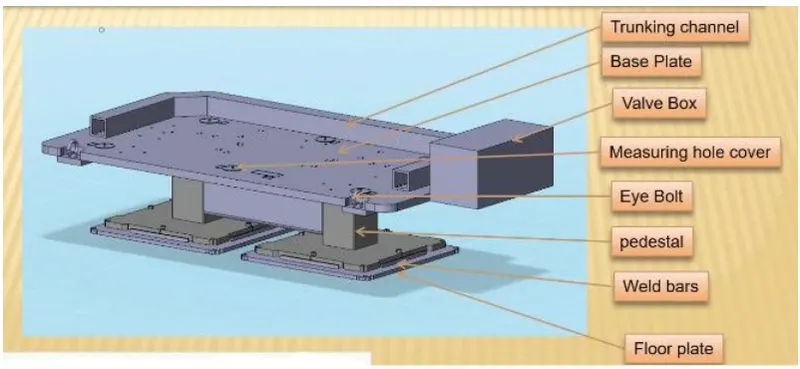
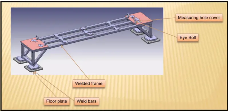
FIG FLOOR_PLATE
WELD BAR
Weld bars are used after the leveling is done by leveling screw. Weld bars are steel plates along the sides of the base plate of a pedestal weld bars are used to position the position permanently.
2.What are the points needed to account for while designing a Base unit?
For designing the base unit, some considerations need to be taken
- WORKING HEIGHT
It depends on the nature of the resources that we are using (manual or auto-machine).
For manual fixtures, we need to consider the working heights that differ from 850mm-1100mm depending on the customer that is using and the workers that are working in the plant and there are some specific standards for different countries. In few countries, human heights are lower than the other countries
If the base structure is made with a base plate having tubular structure welding below it can reach heights 100mm to 250mm .in some cases to reach the working of weld base height we need to provide additional leg structure which may have top & plate welded to the tube
- As a designer, it is important to know how big the Baseplate or Bigger base Welded structure will be handled during the fabrication & handling process. Specific care needs to take care of flatness if the base size is very long.
Fundamentals of Base Plate Design
- A base plate size should cover all the units with its outer periphery including the opening.
- A base plate is preferred to be designed concerning BCS coordinates
- The number of Datum holes depends on the size of the base plate
- Datum holes should be drilled at a nominal value of coordinates and in terms of 50&100(in general (X=100, Y=600, Z=250
- Datum holes should be drilled with dia 100mm away from other units. and it should be covered with a cover plate.
- Depending upon the weight eyebolt size is selected for lifting holes on the base plate. Generally, 4 eye bolt provision is made. You also need to select the location of the eye bolt considering the rope/ belts used while shifting the structure or complete fixture are not damaging any units (rest, clamp, or location units) nearby.
- Only base plate or welded structure Depending upon the component size & weight of the total units you can decide whether you need a fabricated base or just a plate. Mostly fabricated bases are used made of square or rectangular tubes with the plate.
- Most of the OEM makes 4 dowel holes at 4 corners & puts small aluminum plate marking X. Y & Z coordinates of dowel holes. If the base length is too long few OEMs follow the methodology of having holes at a 500 mm distance.
- The best unit of the fixture must be strong enough so that deflection of the fixture is as minimum as possible. This deflection of a fixture is caused because of forces of welding, clamping of the workpiece.
- The base unit of the fixture should have the mass to prevent vibration & chatter.
- The base unit may be built from simple sections so that other units may be fastened with screw or welded necessary. Those parts of the fixture that remain permanently with the fixture may be welded. Those parts that need frequent changing may be held with screws.
- The base unit should be parallel to the floor, to adjust this there should be a provision of the height adjusting mechanism.
3.What is a Dump unit?
- Dump unit is mostly used on different panels where the welds are not achieved easily. sometimes it happens that there are some hard-to-reach panels, and which cannot be fixed by simple units .in such case fix them we will use dump unit
- The first cylinder dumps the assembly carrying clamp mylar, pins, and then this assembly performed the required operations. In this unit, we should make sure that in the open position of the panel we should be able to remove the panel.
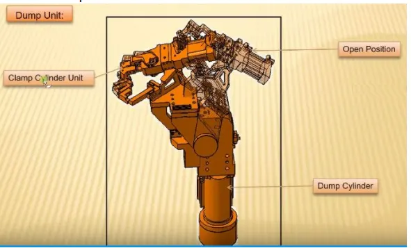
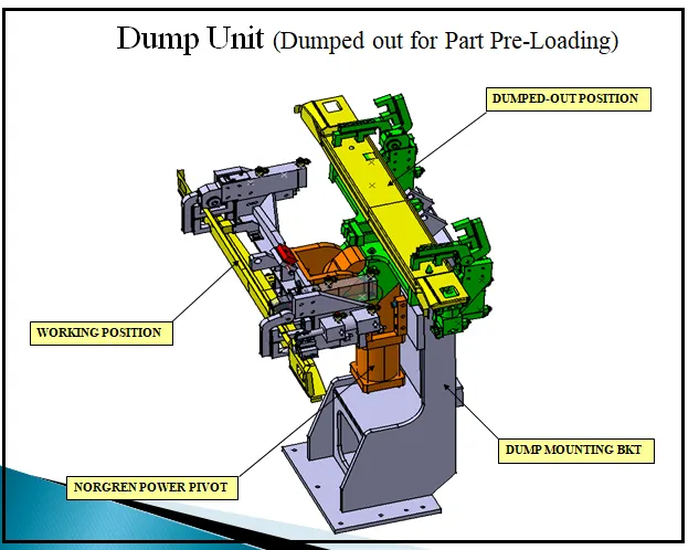
FIG -DUMP UNIT
FUNCTIONS OF DUMP UNIT
- To ensure proper resting of the panel being welded and to restrict its motion
- A dump unit should have two cylinders one is to clamp the mylar at the located point and the other cylinder used to dump the whole unit.
- Programming is the main part of to function dump unit. because when the two cylinders move at the same time it distorts the panel .so at that time programming will play a main role
- In the dump unit, one assembly is fixed and the whole assembly will be mounted on the Dump unit cylinder.
- Cylinder validation is more important in the case of a damp unit as the weight can be too heavy for the cylinder to damp
- In such case, calculations are done and force exerted by the cylinder is checked against the weights of the load being carried
- If the cylinder force is more it is validated or we use a more powerful cylinder.
4.What are the points you need to consider while designing a Dump unit?
As dump unit is complex to design because of a lot of parts, we have to be considerate while designing it as any errors during the designing stage creates a lot of problem at the later stage which would result in loss of time and money and eventually more time and money to rectify the problems. Following are the points we need to consider while designing a dump unit:
The following are the points to be considered while designing the dump unit otherwise it results in errors and waste of time and money
- 3-2-1 principle: Once we have designed the rest of the mylars, pins, and clamps and added a cylinder for clamping. We will check the resting location and clamping of the panel being welded. This will be done by the assembly being dumped onto the panel to operate. It is important because it is the reason why we are creating a dump unit. The positional accuracy of the panel is of utmost importance.
- Mass consideration: The assembly being dumped should have as little weight as possible without reduction in the strength of the assembly. This is because the lesser the weight, the lesser will be the force required to push and pull the assembly. We have to consider the factor of safety as well.
- Time of opening and closing. The time of opening and closing of the clamp should be less. This depends on the power and capacity of the cylinder and the weight of the assembly being dumped. We need to keep it less because if it takes say 2 seconds to open then for that time we will not be able to unload the panel which will increase the cycle time resulting in more idle time.
- Cylinder Validation: Cylinder validation is an important aspect of the dump unit or any clamp unit design because the cylinder should be able to push the load for operation and then pull it back after the operation is complete. The center of gravity of the unit and the distances between the cylinder center lines and end effectors.
- Open Condition: We need to also check the open condition after the cylinder validation because the panel should not fowl with the while removal
5.What is a Slide unit?
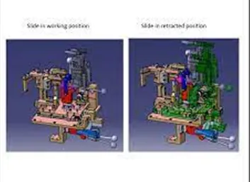
A sliding unit has a clamp or a pin or a rest unit attached to it which slides forward and performs the required operations .on completion of the operations, slide move back.it has a cylinder that pushes the assembly forwards. Assembly is mounted on a plate, which is attached to guide rails. there are sensors on the extreme ends of the slide to see the position of the slide.it has to stop docks on either side of the slide to stop the cylinder at the required position .it has a locking mechanism that ensures that the slide does ni=ot move in a particular position as it may affect the welding quality and may damage the panel slides units are commonly used at places where there are space constraints
Slide units are positions using which are used to position the fixture, welding gun unit robots into position for future operations.
-slide units can be classified into two types on the also of the type of guide-ways used as
1. Hardened guideways
2. LM Guideways
3.CNCslides
-it may also be classified depending on application as
1. manual slides
2. Vertical Slide
3Angular Slide
-Slide units are used when we have some space constraints. So, we don’t have space to design different special units& to assemble them .in those cases we use sliding units.
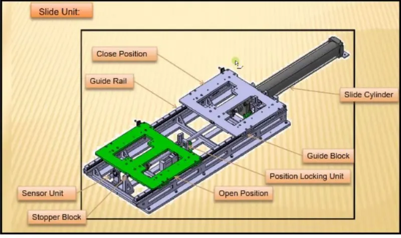
SLIDER UNIT
6.What are the points you need to consider while designing a Slide unit?
A sliding unit comes under the category of complex unit .few points that need to be considered while designing a slider unit
1 Weight carrying Capacity
There are different kinds of guide rails available in the market, each having a different load capacity. Hence, we calculate the weight of our assembly and calculate the weight capacity of the rail Hence, we choose rail based on its load-carrying capacity
2 Push and Pull Forces
We need to check the push and pull forces and check if it is enough to push and pull the slide especially when the slide is at an inclination
3 Locking Mechanism
The locking mechanism ensures that the slide does not move while it is at an open or retract position. If the side moves while welding, it can damage the panel as the positional accuracy will be hampered
4 Stopper Blocks
Stopper blocks are used to stop the slide at the required position. It is important as if the slide unit has restarts and pins they need to be stopped at their respective position for proper resting and location. Without a stopper, it may dent the panel
5 Sensor Unit
The sensor unit helps to check the position of the slide. When the operation is going to start the operator pushes the button and the slide moves forward, the sensor gives this signal of the presence of the unit to the PLC which then performs the next operation
6 Stroke
We need to select the length of stroke based on the work area we want to get cleared.
7 the only moving parts are the one the slides, so we need to check the following with a gun or other unit nearby only after this has been checked that we can approve the design.