Week 7:- Base Unit Design Challenges 1

Automotive BIW Fixture Design using CATIA V5
Report
By Ravi Ahuja
Q1.
Base Unit: A base unit is a unit designed to mount all other units(Clamp Unit, pin unit, rest unit, etc) of the tool, also other parts necessary for a tool like pneumatic vlve box, trunking cable path will also be mounted onto a baase unit.
The base unit is fundamental component of the fixture because all other components are mounted oer it so every fixture has a base unit.
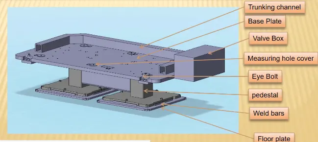
Typical parts of base units are:
1. Baseplate:
The Base plate is a machined plate of 25 to 40 mm thickness made of steel and aluminium, to which the holes are drilled to mount the individual units likeCalmp, Pin units etc.
2. Pedestal:
A pedestal is a part that connects the base plate to the floor plate. A pedestal is a standard part in general and in some cases it can be a welded frame integrated with the base plate.
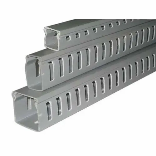
3. Trunking channel:
A trunking channel is a duct htat accomodates all the pneuatic and electric hoses and wires for the units of the tool.
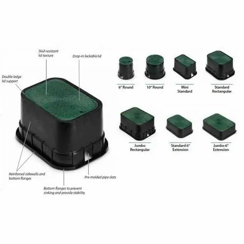
4. Valve box:
The valve box is the standard part that will accmodate all the pneumatic valves for the units. The valve box is the box that includes different solenoid valves. The pneumatic fixtures work on air pressure provieded to it.
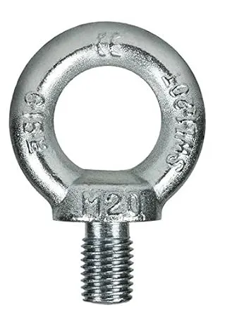
5. Eyebolt:
Eyebolts are used for the trnsporting of the tool, using lift hooks, forklifts holes will also be provided in some areas for transporting purposes. For example, we usually use M20 bolts that are bolted on the base plate.
Q2.
1. Working height: It depends on the nature of the manual or robotic welding fixture. For manusal fixture we need to consider the working height 850-1100 mm depending upon the working height of the worker standrd of a specific country will apply.
If the base structure is made with a base platehaving a tubular strucutre welded below it we can reach the height of 100 to 250mm. In this case to reach the working welding height we need to provide additional leg structure which may have top and plate welded to tube.
2. As a designer it is important to know how big base plate or bigger base welded structure will be handled during hte fabrication and handling process.
Fundamentals of base plate design:
- A base plate should cover all the units with its outer periphery including opening.
- A base plate is referred to be designed with respect to BCS coordinates.
- A base plate should be drilled with datum holes/ measuring holes in line with a pitch of 1000mm in general.
- The number of datum holes depends on size of base plate.
- Datum holes should be drilled at nominal values of coordinates, & in terms of 50 and 100.
- Datum holes should be drilled with dia 100 mm away from other units.
- Datum holes should be covered with cover plates.
3. Depending upon the weight eyebolt size is selectedfor lifting holes on the base plate. 4 eye bolts provision is made. You also need to select the locationof the eye bolt considering the rope/belts used while shifting the structure or complete fixture.
4. Only base plate or welded structure developing upon the component size and weight of total units you can decided whether you need a fabricated base or just a plate.
5. Most of OEM makes 4 dowel holes at 4 corners and put small al plate marking X Y Z coordinatesof dowel holes.
6. The best unit of the fixture must be strong enough so thatdeflection of fixture is minimum as possible.
7. The base unit of the fixture should have the mass to prebvent the vibration and chatter.
Q3.
Dump Unit
Sometimes it happensthat htere are some hard to reach panels and which cannot be fixed by simple units.
A dump unit can have more than one cylinder to perform such operation. The first cylinder dumps the assembly carrying clamp mylars, pins and then this assembly performs the required operation.
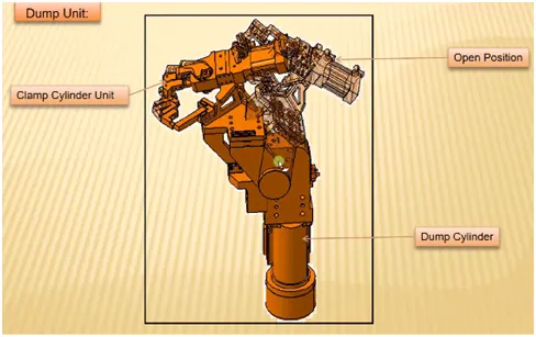
Functions of dump unit:
- To ensure proper resting of the panel being welded and to restrict its motion.
- To ensure ther is no rotation in the panel nd to fix iteither by pins or side block.
- To ensure ther is enough clamping force in the cylinder so that it doesnt move while welding.
- Dump unit should have correct shimming for adjustment of the panel.
- A dump unit can have a slide cylinder or a clamp cylinder attached to it.
Q4.
Points to consider while designing a dump unit:
1. 3-2-1 priciple: The 3-2-1 principle states that the six locators are sufficient to restrict the required degree of freedom of any work piece. In this, motion is restricted using clamps and locators. A three pin base can restrict five motions and six pins restrict nine motions.
2. Mass: We need to make sure that the assembly being dumped should have less weight as possible without compromising the strength.

3. Time of opening and closing: We also need to keep in mind that the time of closing and opening the clamp should be at least possible and this will depenf on the power of the cylinder and the weight of assembly being dumped. We need to keep it less because if it takes say 2 secs to open then for that time we will not be able to unload the panel.
4. Open condition: We also need to check the open condition of the clamps after cylinder vlidarion because the panel should not fowl with the unit.
Q5.
Slide unit:
Slide unit are positioning units which are used to position the fixtures, weld gun, units, robots into position for further operations.
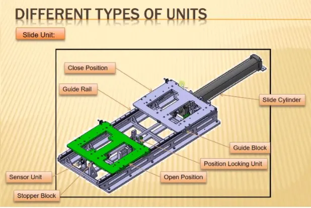
It has a cylinder that pushes the assembly forward. For precision operation ball screw servo motor is used to move the slide forward and backward.
Assembly is mounted on a plate that is attached to guide nails.
There are sensors on the extreme ends of the slide to sensethe position of the slide.
It ha stop dock on either side of the cylinder at the requires position.
It has a locking mechanism which ensures that the slide does not move ina particular position as it may affect the welding quality and may damage the panel.
The opeing and closing of the slide should not fowl.
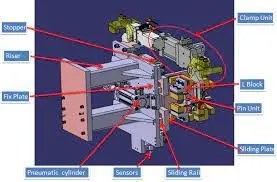
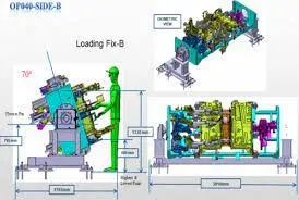
Slide units are used when we have some space constraints. So we dont have space todesign different special unit and to assemble it in those cases we use a sliding unit. Sometimes there are too many small panelsnear each other and not enough space as each panel requires resting, location using 2 pins, clamping and sensing.
Q6.
Points to consider while designing the slide unit:
Weight carrying capacity:
Different kind of rails are present in market and we calculate the total mass of the assembly and then we take the rail according to that data.
Push Pull forces:
We need to check if its enough to push and pull the slides.
Locking mechanism:
It ensures that slide doesnt move while it is at an open or close position.
Stopper block:
They aee used to stop thr slide in required position and prevents the sudden movement.