Week 7:- Base Unit Design Challenges 1
1. What is the Base Unit? What are the typical parts of the Base Unit?
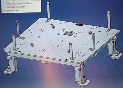
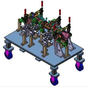
A Base unit is designed to mount all the other units(Pin,Rest, Clamp,Pin - clamp units) of the tool and other parts include pneumatic valve box, trunking cable.
Parts of Base Unit:
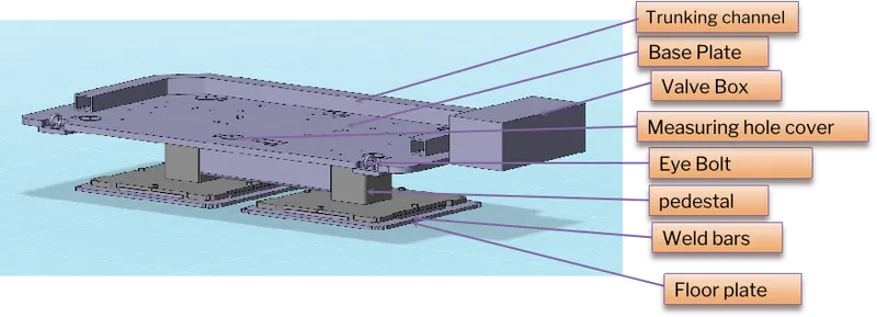
- Trunking channel: All Pneumatic channels , electrical hoses and wires of the units are accommodated in the trunking channel.
- Base plate: It is a machined plate of 25 to 40 mm thickness made of steel and aluminium, on which the holes are drilled to mount the individual units.
- Valve box: It is a standard part that accommodates the pneumatic valves for the units.
- Measuring hole cover: It is the cover of the datum hole.
- Eyebolt: It is used for the transporting of the tool, using lift hooks, Forklift holes will also be provided in some cases for transporting purposes.
- Pedestal: It is the part that connects the base plate to the floor plate. It is the standard part in general, and in some cases, it can be a welded frame integrated with the base plate.
- Weld bars: These are the support structures between the pedestal and floor plate.
- Floor plate: It is grouted to the floor with a fixed bolt on the ground. Floor plates are also called foundation plates.
2. What are the points need to account while designing a Base unit?
- Base plate is preferred to be designed for BCS coordinates.
- Base unit should cover all the units with its outer periphery including openings.
- Base plate should be drilled with datum holes/measuring holes in line with a pitch of 1000 mm in general.
- Number of datum holes is dependent on the size of the base plate.
- Datum holes must be drilled in nominal values of coordinates and terms of 50 and 100.
- Datum holes should be drilled with a diameter of 100 mm away from other units.
- Datum holes should be covered with a cover plate.
- There must a minimum space for the trunking channels.
- The weld gun position and the weldment have to be checked. A minimum of 5 mm gap must be present between the gun and the units.
3. What is a Dump unit?
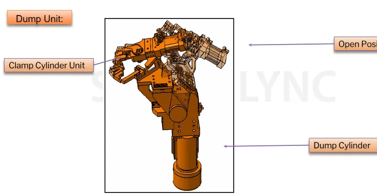
A dump unit can have more than one cylinder to perform such an operation. The first cylinder dumps the assembly carrying clamp mylars, pins and then this assembly performs the required operation. In this unit, we should make sure that in the open position of the panel, we should be able to remove the panel.
Functions of the dump unit:
- Have to check the correct resting position of the panel being welded and constrain its motion.
- The panel rotation must be constrained with all DOF
- It must have correct shimming for adjustment of the panel.
4.What are the points you need to consider while designing a Dump unit?
Dump unit is a complex unit. The design of the dump unit must be done with almost care and preciously.
A Dump Unit is a unit in which an assembly of other units like pin unit, rest unit, clamp unit etc is mounted on a large bore cylinder, sufficient enough to validate the total load due to various units. A dump unit is basically used in conditions where, we have constraint to mount a panel from above the main part or constraints with gun positioning.
Following points need to be considered while designing a dump unit
- Dump Unit need not necessarily to be used in fixture design, it depends on the conditions & various constraints.
- Dump Cylinder validation must be done as per the total weight mounted on the cylinder Shock absorbers must be implemented to avoid vibrations.
- Proper opening & closing of dump unit must be checked. Frame mounting the dump unit should have strength to bear different static & dynamic loads.
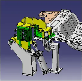
5. What is a Slide unit?
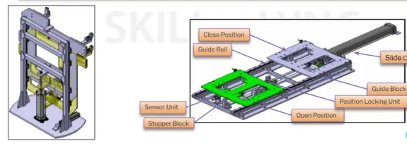
- A Slide Unit is a unit in which an assembly of other units like pin unit, rest unit, clamp unit etc is mounted on a sliding mechanism, with the help of cylinders.
- A Slide unit is basically used in conditions where, we have constraint to mount a panel to slide in to the main assembly or constraints with gun positioning.
6. What are the points you need to consider while designing a Slide unit?
- Slide units may further be classified into three types based on the prime mover used as manual slides, Hydraulic/pneumatic slides, and CNC slides.
- It may be further classified as Horizontal, Vertical, and Angular slide units depending on the application.
- Slide Unit need not necessarily to be used in fixture design, it depends on the conditions & various constraints.
- Slide units are positioning units that are used to position the car part, fixture, weld gun robots into position for further operations.
- Slide units may be classified into two types based on the type of guideways used as hardened guideways and LM guideways.
- Slide Cylinder validation must be done as per the total weight & force exerting on the cylinder.
- Shock absorbers must be implemented to avoid vibrations. Proper opening & closing of Slide unit must be checked.
- Sensors should also be provided to ensure the position of slide unit, in automation.
- Mechanical Stoppers need to be provided for positioning.
- Sliding mechanism can be formed through various means, such as, LM-rail & guide, ball screw, manual, cylinders, motors etc.