Week 7:- Base Unit Design Challenges 1
1) What is a Base Unit? What are the components of a base unit?
Base unit holds all other units and tools necessary for a fixture assembly. Units like pin unit, clamp unit, etc. are loaded on the base unit. The individual parts of the base unit are welded together. The base unit is designed depending on the requirement of the fixtures.
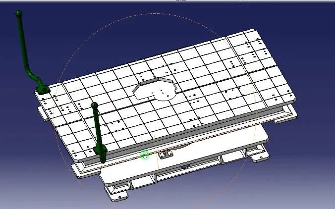
Parts of the Base unit:
Base Plate:
It is usually made of aluminum or steel with thickness ranging from 25mm to 40mm. Holes are provided by drilling for mounting for different units that are required to be mounted.
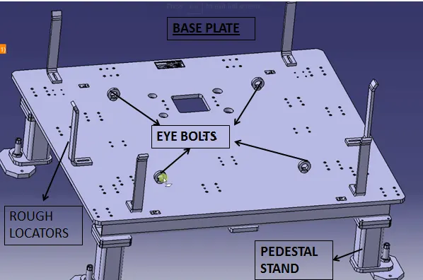
Pedestal:
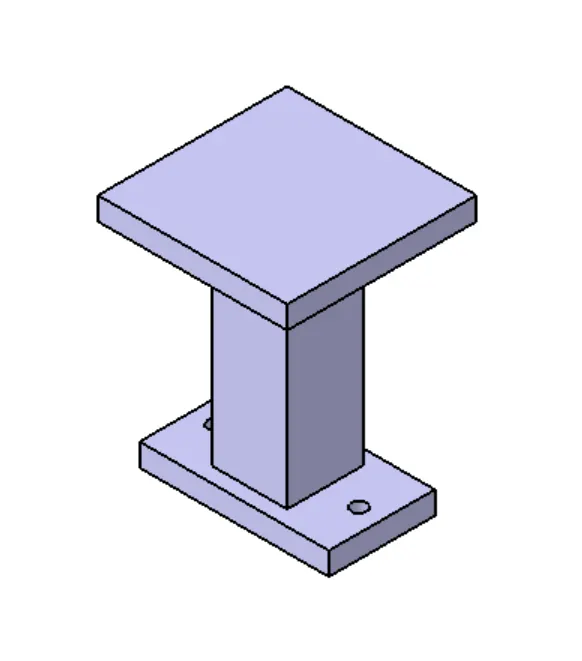
It is a standard part and is welded together with the base plate, it connects the base plate to the floorplate. The number of pedestals required is depended on the load carried by it. The height and size defer w.r.t the same. The height of the pedestal is decided such that the working surface comes to a height of 900-1100mm. This height is needed for ergonomic purpose, as the operator needs to operate at a safe height which can cause less fatigue.
Trunking Channel:
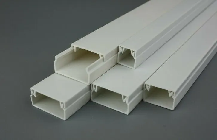
It is used to guide the wires and cables required in the assembly. It helps with improving the aesthetics of the assembly as well as organize it in a way which is easy to understand at the time of inspection. It also protects the wires from other possible damages whiles different operations are done.
Valve Box:
It accommodates all the pneumatic valves for the unit. The valve consists of different solenoid valves. The pressure for operating different cylinders is controlled through the valve box. The cables needed is connected through the trunking channel.

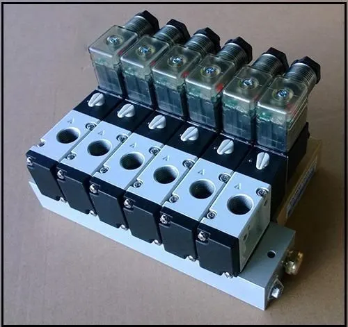
Eye Bolts:
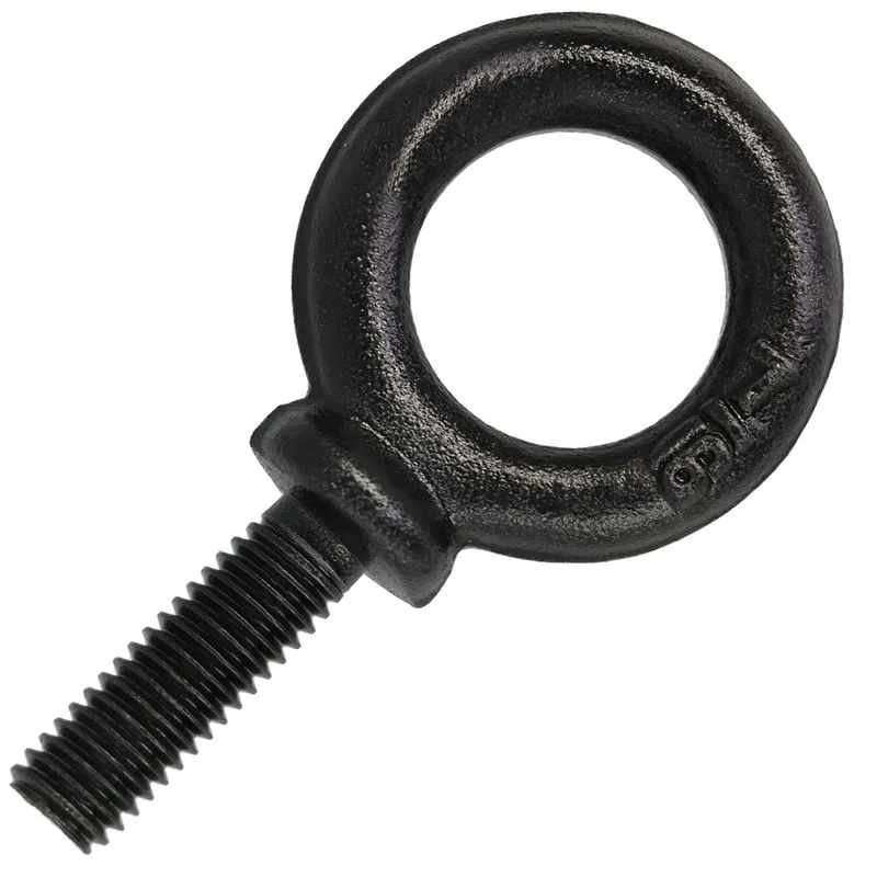
While transferring the unit from one area to another, it needs to be lifted with the help of different equipment. Hence, for lifting purpose, an eye bolt is provided in the unit where hooks can be attached for easy lifting of the unit.
Floor Plate:
Also know as foundation plates, these are bolted to the ground. There is a clearance of 10mm maintained for leveling. Once it is done, weld bars are used to permanently weld the part.
2) What are the points needed to be kept in mind while designing the base plate?
- Working Height:
- The working height of the component needs to be around the height of 900-1100. This height is determined by the average.
- The height is provided by adding pedestals under the base plate. The height of these pedestals depends on the cylinders used of the equipment used for the particular unit.
- Base Plate
- The base plate should cover all the units mounted on it as well as the opening positions of the units.
- The datum holes need to be of 1000mm pitch. The number of holes depends on how big the base plate is.
- The hole coordinates need to be in multiple of 50 for easy manufacturing.
- The holes should be at least 100mm away from all the units.
- Eye Bolt: Generally, 4 eye bolts are provided for lifting of the assembly. Then location of these bolts is selected such that it does not harm or damage the units placed on the base plate. Depening on the weight of the unit, the eye bolt is slected so that is can lift the weight of the unit.
- The base unit should be strong enough to resist the deflecting forces caused due to various operation on the unit.
- The base unit should be stable enough to cancel out the vibrations.
- Parts that need frequent inspections should be bolted or screwed together and parts that need not be changed again can be welded.
- The entire unit needs to be parallel to the floor and needs to have allowance for adjustment.
- Thickness of base plate should be ideally around 8-10mm so that it is flat even after machining process are carried out on it.
- Most OEMs have dowel holes at corners to put marking of the holes co-ordinates.
- The base plate should be parallel to the floor and adjustment provision should be present in cases it is not parallel.
- In case the base plate is very big, care needs to be taken that the base plate is flat and does not bend easily.
3) What is a dump unit?
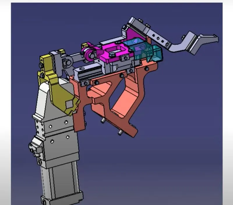
Dump Units are used to operate on panel which are complex and hard to work on. They usually have multiple cylinders to perform the operations. The construction of dump unit is complicated and hence care should be taken that the panel can be removed when the dump unit is in open position,
Dump unit is used for the following purposes:
- To ensure the parts are properly locked with the help of pins or magnets.
- Dump units should provide proper shimming for adjustment.
- The clamping should be done with adequate amount of force. It should not exceed the required amount of force.
- The parts should be rested properly.
- It can have multiple cylinders or slide units.
- The weight should be monitored so that it doesn’t weigh too much.
4) What are the points you need to consider while designing the dump unit?
Since dump unit is a complex unit, it is necessary to design the unit carefully. Any kind of error can cost a lot of capital.
Mass:
The mass of the dump unit needs to be controlled so that it doesn’t affect the strength of the entire unit. Having a lighter assembly is beneficial as it reduces the force needed to move the components.
Timing:
The opening and closing time should be kept minimum and should be adjusted such that it reduces the cycle time as well as does cost much to provide the power required for the operation of the same.
3-2-1 Principle:
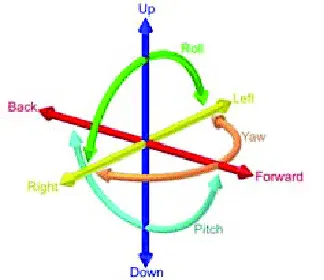
- This principle is used for locking the 6 degrees of freedom of the component. A resting unit locks 3 degrees of freedom. The up and down movement and 2 rotational degrees of freedom.
- For locking all 6 degrees of freedom, 3 supports are placed to form the first datum.
- Next, we add clamping units to and add minimum of 2 pin units to arrest all 6 degrees of freedom.
Cylinder Specifications:
It is necessary that the cylinder used can handle the amount of weight it needs to operate. For this, the C.G of the part needs to be considered, through which the stroke length and the capacity of the cylinder is determined.
5) What is a Slide Unit?
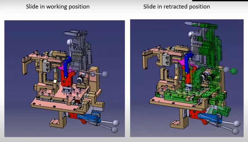
It is usually used where there is space constrain, it can be a pin unit or a clamp unit. It slides forward or backward. The stopping of the slider is controlled with the help of sensors. These are basically positioning units.
At times when there are a lot of panels in the same area, slide unit comes in handy. The assembly is attached to guide rails for proper movement. For smooth movement, the guide rails need to be lubricated well.
The slides can be moved by various means such as manual slides, CNC slides or even hydraulically. It can be horizontal, vertical or angaled depending on the are it needs to work in.
6) Points to consider while designing slide unit.
Load carrying capacity: The guide rails are bought depending upon the weight of the entire unit.
Push and Pull forces: The force required to pull or push the slide unit needs to be calculated, especially if the slide unit is placed with an inclination.
Locking mechanism: There needs to be a locking mechanism to make sure the slide does not move when it is in the closed position.
Stopper block: The slide unit have various parts like mylars and pins, hence it is necessary that it stops at the correct position. Otherwise, it may damage the panel.
Sensor unit: Sensors are used to control the moments of all the or important parts so that the moments are precise and chances of errors are minimum.
Stroke length: The stroke length needs to be decided so that the area can be cleared.
Open position: The open position needs to be checked so that we can avoid the fouling of the parts.