Week 7-12-Creation of 1D Connectors Challenge
MESHING OF SHEET METAL COMPONENT AND CONNECTION OF THE COMPONENTS USING APPROPRIATE CONNECTORS
Aim :
- Make a proper geometric clean up on the surfaces if there is any damaged surfaces.
- Maintain a Proper mesh flow with less tria concentration.
- To achieve exact quality criteria as given in the question.
- Mesh the component properly with clean up tools to get proper mesh flow.
- Connecting the components with the appropriate connectors.
Procedure :
Step 1 - Geometry Import
- Importing a given CAD geometry into hypermesh.
- There are file formates like IGES, STEP, Parasolid where we can import these file formats into any CAD,CAE Softwares.
- But in hypermesh we can only import three file formates like IGES [Initial Graphics Exchange Specification], STEP [Standard for the Exchange of Product Model Data], Solidworks as shown in the figure below.
Step 2 - Examining
- Before working on the model.We have to organize the many components to single individual components, so that it's easy to work on and then check the geometry if there are any errors. some of the geometrical errors are as follows.
- Damaged Geometry.
- Free edges in unnecessary areas.
- Unnecessary points on the lines.
- Unnecessary Connections and connectivity error.
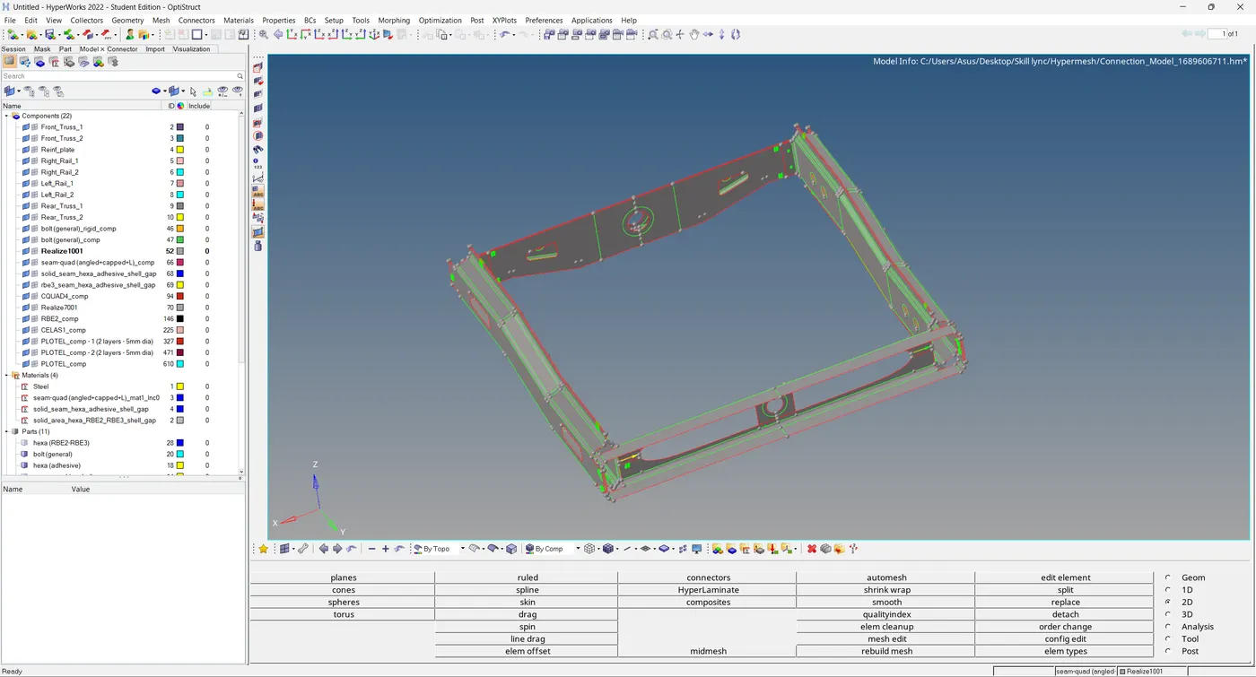
- Organizing the CAD model to as shown in the below figure.
Step 3 - Extracting Midsurface
Auto Midsurface extraction
- Since the model is a sheet metal component there is no need to extract Mid surface for the component.
Step 4 - Assigning material property to the components
- To assign a property,Right click on the feature tree panel/right click>">>>create>">>>property.
- Do the same thing for the material also.
- After creating property and material.Select the property and give the material which you have created and thickness to the property.
- And then go and assign the property to the component which you have exracted the mid surface from it.
Assigning Property
- If we have symmetry in the components.We can cut into half and we can reflect the surface and mesh on the other side.By doing like
this,we can save lot of time instead of doing both sides. - Since the model is not perfectly symmetric, meshing is done for the whole model.
Step 4 - Manual Clean Up
Manual clean up is necessary to achieve a things like
- Proper mesh flow.
- Feature capturing.
- To eschew the elements failing for the minimum length.
- For surface deformations.
- For connectivity errors.
4:1 Extracting the midline for Upper Body.
- We have to toggle all the split lines which are less than minimum length.
- We have to go [Midline option>">>>geom>">>>lines>">>>midline].
- We have to select two fillet edges on the hemming portion and then create a mid line.
[Note : If it is necessary to extract the midline in the hemming regions.You can extract or it's fine.]
Extracting Midline in hemming region
- If there is any unnecessary lines,We can toggle that edges to get a proper mesh flow.
- In this component.In the fillet region,there some unneccessary shared edges so,toggle that edges also.If we
mesh without toggling the edges,the element's will fail.
Step 5 - Perform Mesh on the surfaces.
- Enter the quality criteria what they given for the component's.
- Tool bar → preferences → criteria file settings → checks for the element criteria →Enter values → apply → ok.
- Save the criteria file settings for that component as it facilitates easy loading of the required criteria for analysis.
Target Element size - 5 Units
| S.N | Quality Criteria | Value |
| 1 | Aspect Ratio | 5 |
| 2 | Skewness | 45 |
| 3 | Warping | 15 |
| 4 | Taper | 0.5 |
| 5 | Min. Length | 2 Units |
| 6 | Max. Length | 8 Units |
| 7 | Min angle Quad | 45 |
| 8 | Max angle Quad | 135 |
| 9 | Min angle Tria | 30 |
| 10 | Max angle Tria | 110 |
| 11 | Tria % | 15 |
Try to achieve the quality criteria mentioned above in the table.
Conditions to be followed while meshing.
- Feature Capturing.
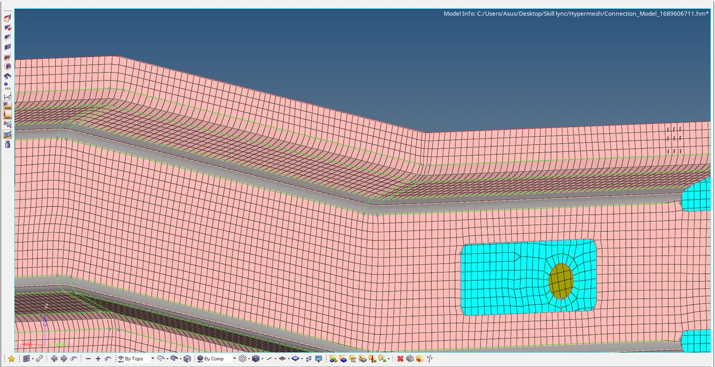
- Feature capturing is must while meshing.All the nodes must be connected to the shared edges.
Feature Capturing
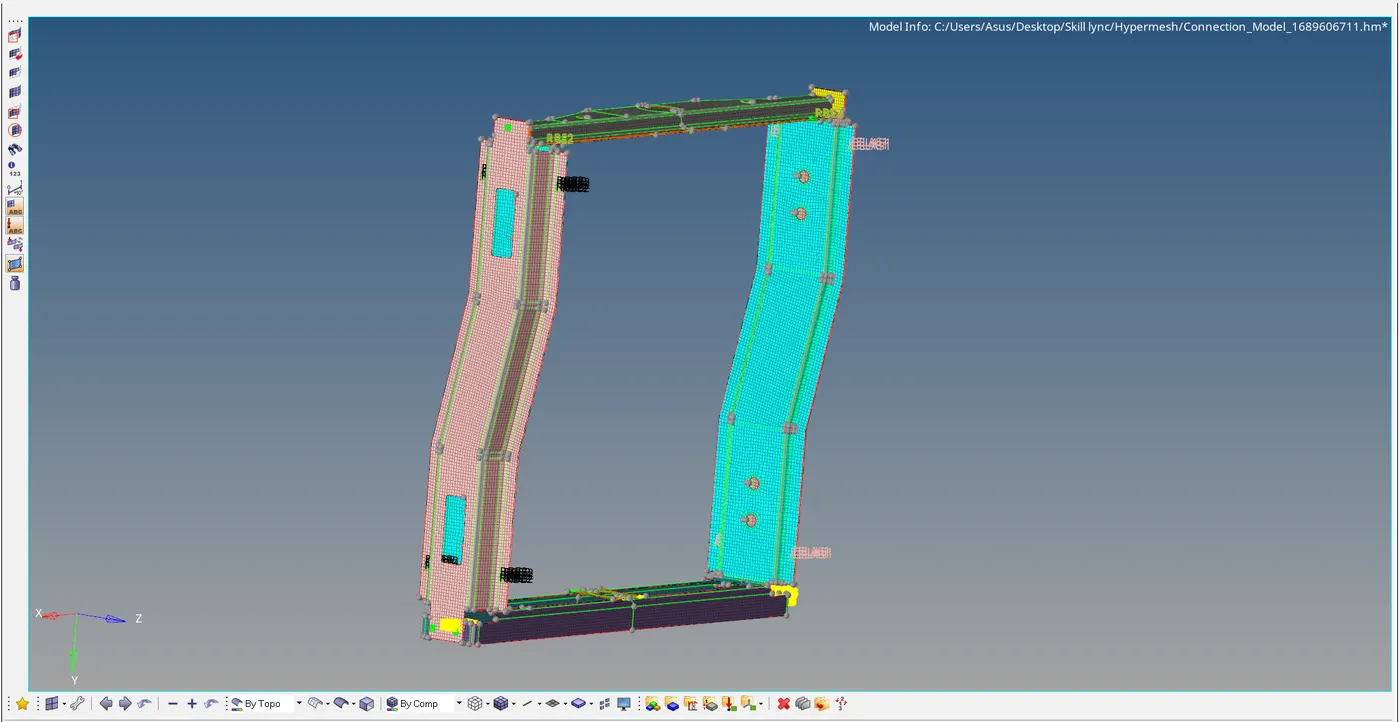
- Mesh Flow
Mesh Flow
- Quality Criteria
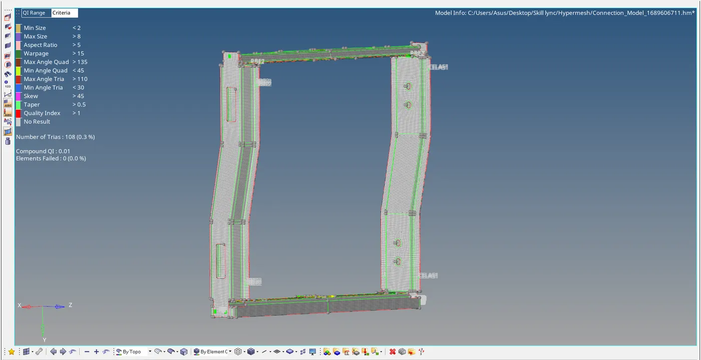
Quality Criteria
- Tria Management
- Avoig higher number of trias.
- Important Parameter's in tria management
- No trias in corner's or edge's.
- No opposite trias.
- No back to back trias.
- No trias in fillets or hemmings(We can have minimum but anyhow try to avoid).
- No rotational quads.
- No trias should share a boundary with feature line.
- Connectivity between elements.
- Split and perform the mesh.
- Use mixed type mesh for irregular shaped surfaces and quads only for rectangular/square surfaces(Opposite sides should be parallel and equal).
Begin meshing the surfaces
- Start meshing from the centre regions or from least free edges.You will get proper mesh density and proper mesh flow.
- If the mesh is not proper since remesh or rebuild the mesh by using this two tools.
Using quality index clean up tools
| SI.NO | Tool Name | Purpose of the Tool |
| 1 | Place Node | Move the node along the plane or curvature of the surface or away from surface. |
| 2 | Swap Edge | Each time if we click an edge, it switches to the next valid configuration. |
| 3 | Element Optimize | To move the midnodes attached to the element we are optimizing, enabled the with attached midnodes checkbox. |
| 4 | Smooth | It is used to improve the element quality of the surface. |
| 5 | Split/Collapse Edge | To use the split edge tool, left-click on an edge. HyperMesh splits the elements that share the selected edge in a way that will achieve the optimum quality. |
| 6 | Drag Tria Element | To use the drag tria element cleanup tool, left-click on a tria element and drag it to a desired location. HyperMesh highlights the selected tria element in pink.Drag both trias to combine when they are facing opposite direction. |
| 7 | Split Quad Element | To split a quad element, left-click on the quad element you wish to split. HyperMesh splits the quad element into two tria elements. |
| 8 | Combine Tria Element | To combine two tria elements, left-click on their shared edge. HyperMesh combines the two tria elements into one quad element. |
Other Clean Up tools
- Distance
- Translate
- Align Nodes
a. Distance
- Geometry → Distance → two nodes → enter the value.
- The Distance panel to determine the distance between two nodes/points or the angle between three nodes/points, or to change
distances or angles.
b. Translate
- Tool → Translate → Nodes → N1,N2,N3 → Translate +/-
- This tool is used to fix the warpage.
c. Align Nodes
- Geometry → Node edit → align mode → 1st node → 2nd node → 3rd node → align.
- Select a node that defines one end of the imaginary line.
- Select a node that defines the other end of the imaginary line.
- Once both nodes are selected, now we can pick the nodes that we wish to align.
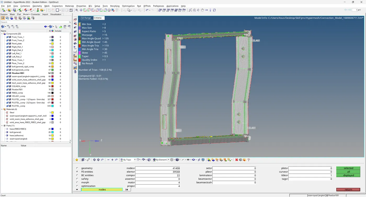
Check Nodes
- Tool → Count → Nodes → right click select all → press selected ( no of nodes will be displayed)
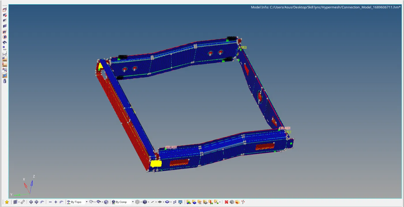
Check Normals
- Top side of surface must be in blue colour.
- Bottom side of surface must be in red colour.
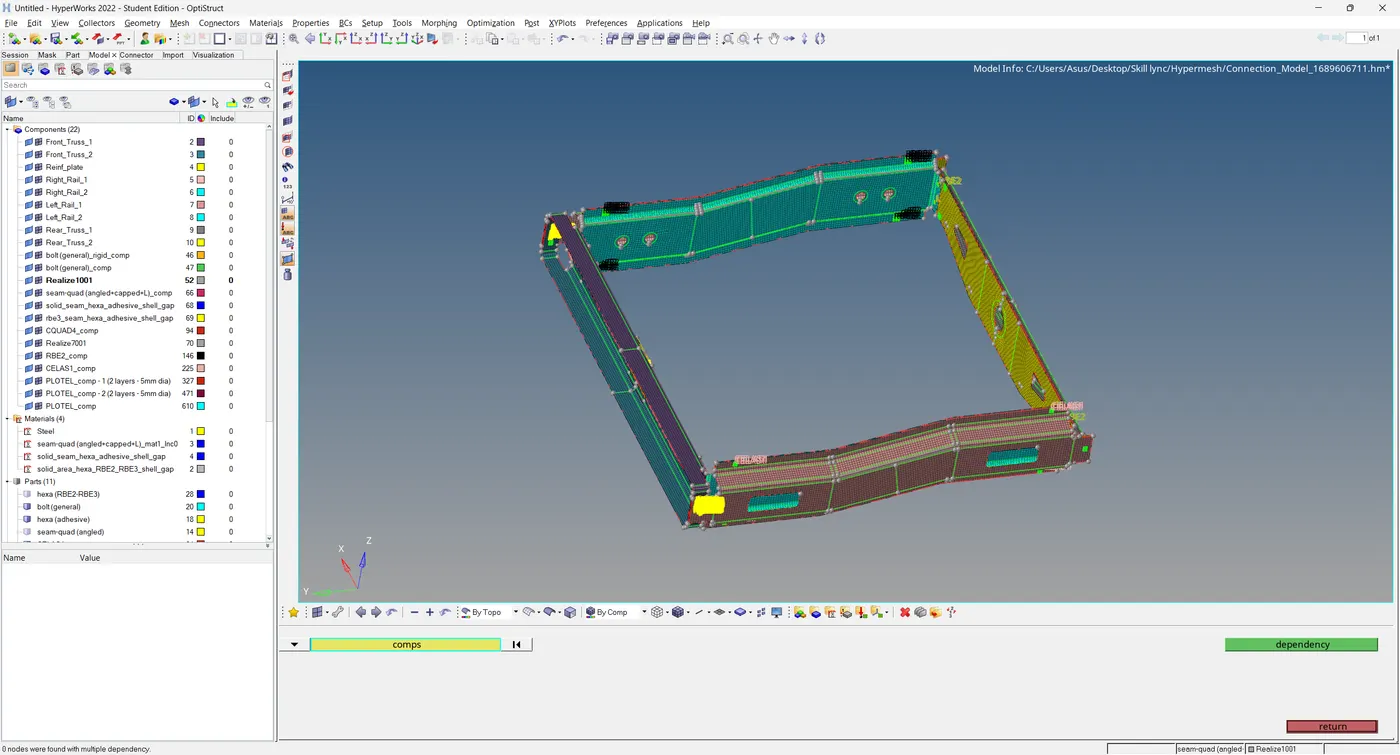
Check dependency
- Check whether the nodes dependent on multiple nodes as this can cause issue during the analysis, So there must 0 nodes containing multiple dependency.
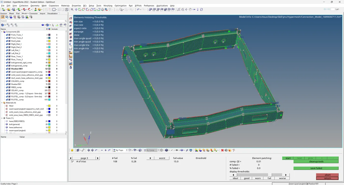
Check tria percentage
- Check whether the tria percentage is within the given tria concentration in the quality criteria.
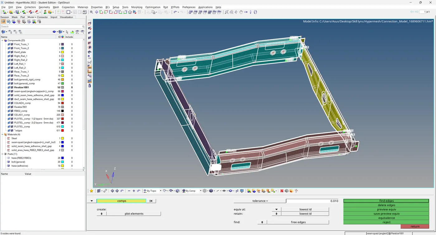
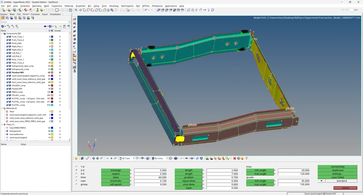
Check for edges and duplicates
Conclusion :
- Every component has been meshed with proper good mesh flow and attained the quality criteria as per given below.
- Every tria conditions has been followed in this model and completed successfully.
Connections :
- Every component is connected by the appropriate connectors as required in the table below.
1. Right_Rail_2 & Front_truss_1:- Seam-Quad(angled+capped+L)
2. Left_Rail_2 & Front_truss_1:- Quad elements
3. Front_truss_2, Front_truss_1 & Right_Rail_1:- Spot weld with 2 Layers and 5 mm Diameter
4. Front_truss_2, Front_truss_1 & Left_Rail_1:- Hexa (Adhesive)
5. Rear_truss_2 & Right_Rail_2:- Bolt Connector
6. Rear_truss_2 & Left_Rail_2:- Bolt Connector
7. Right_Rail_1 & Right_Rail_2:- Spot-weld with Rigid Elements
8. Left_Rail_1 & Left_Rail_2:- Spot-weld with Spring Elements
9. Rest all the components left Join them with suitable connectors
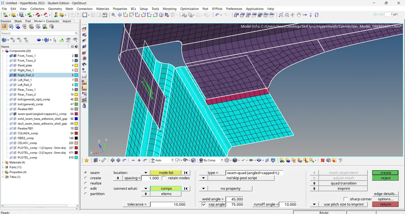
Step 1 : Right_Rail_2 & Front_truss_1:- Seam-Quad(angled+capped+L)
- The two components are joined by first selecting the 'Connectors' option in the 1D window and selecting the 'Seam' option which opens up a window for entering the further specifications. The type of Seam joining required is selected in the type window (Seam-Quad(angled+capped+L)).
- The nodes and components are selected where the attachment to be done. The tolerance between the components, and the specification of the connection like weld angle, cap angle etc is provided and the create button is clicked.
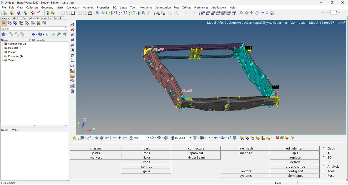
- The connection obtained is shown in the figure below.
Step 2 : Left_Rail_2 & Front_truss_1:- Quad elements
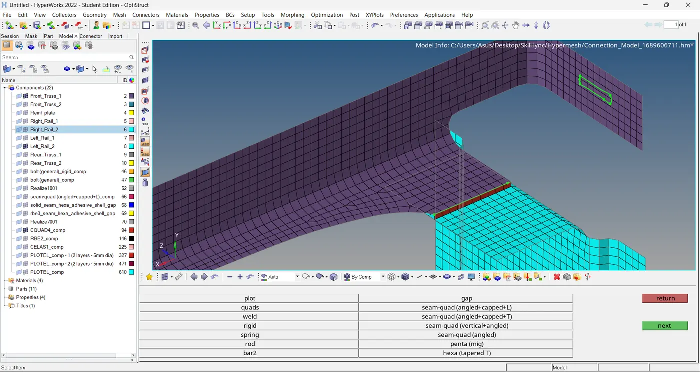
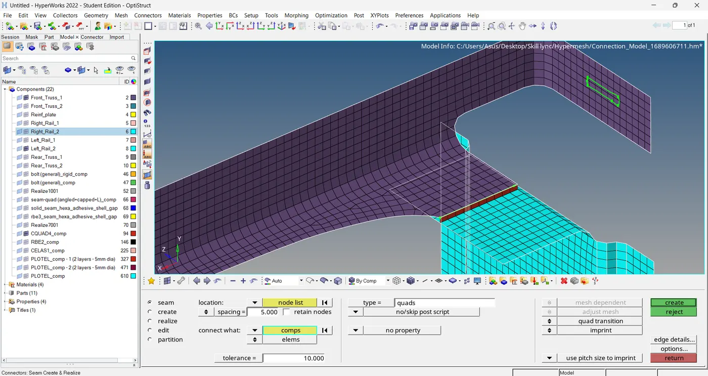
- The two components are joined by first selecting the 'Connectors' option in the 1D window and selecting the 'Seam' option which opens up a window for entering the further specifications. The type of Seam joining required is selected in the type window (Quad).
- The nodes and components are selected where the attachment to be done. The tolerance between the components, and the specification of the connection like Spacing is provided and the create button is clicked. The value provided for Spacing is usually the target element length.
- The connection obtained is shown in the figure below.
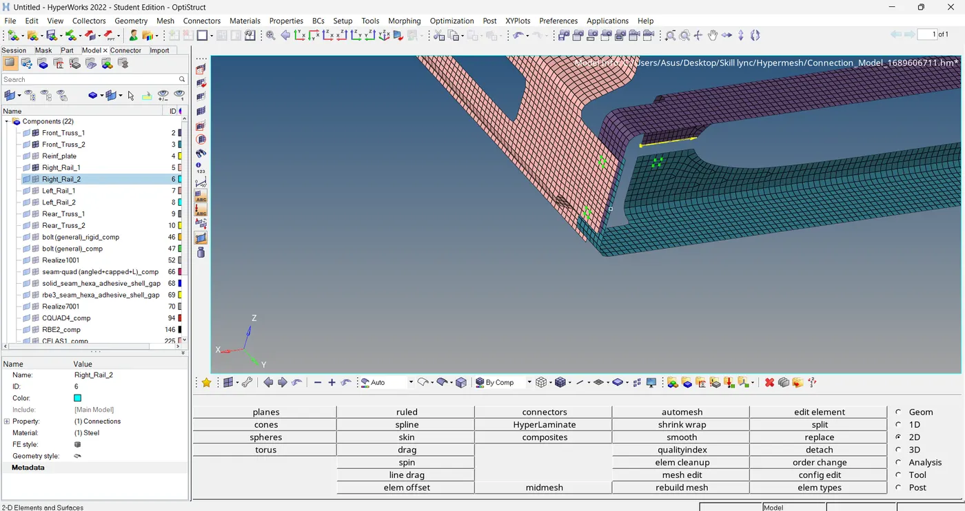
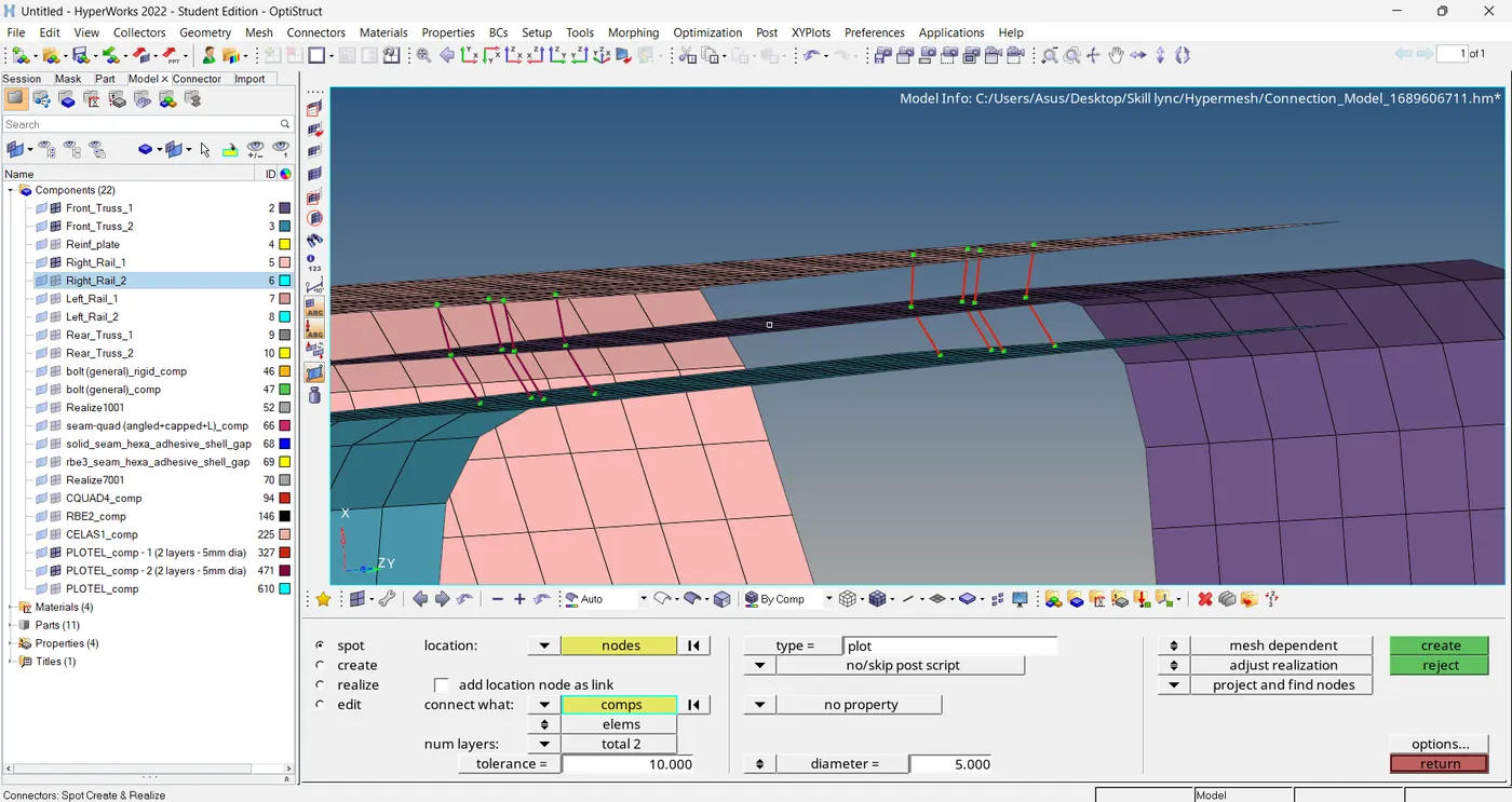
Step 3 : Front_truss_2, Front_truss_1 & Right_Rail_1:- Spot weld with 2 Layers and 5 mm Diameter
- The two components are joined by first selecting the 'Connectors' option in the 2D window and selecting the 'Spot' option which opens up a window for entering the further specifications. The type of Spot weld joining required is selected in the type window (Plot).
- The nodes and components are selected where the attachment to be done. The tolerance between the components, and the specification of the connection like number of layers and Diameter of the weld is provided and the create button is clicked.
- The connection obtained is shown in the figure below.
Step 4 : Front_truss_2, Front_truss_1 & Left_Rail_1:- Hexa (Adhesive)
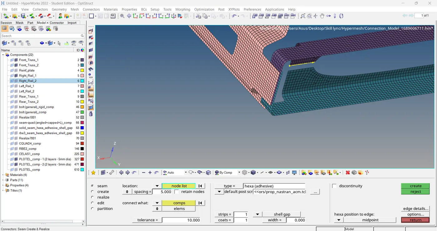
- The two components are joined by first selecting the 'Connectors' option in the 1D window and selecting the 'Seam' option which opens up a window for entering the further specifications. The type of Seam joining required is selected in the type window (Hexa (Adhesive)).
- The nodes and components are selected where the attachment to be done. The tolerance between the components, and the specification of the connection like Spacing is provided and the create button is clicked. The value provided for Spacing is usually the target element length.
- The connection obtained is shown in the figure below.
Step 5 : Rear_truss_2 & Right_Rail_2:- Bolt Connector
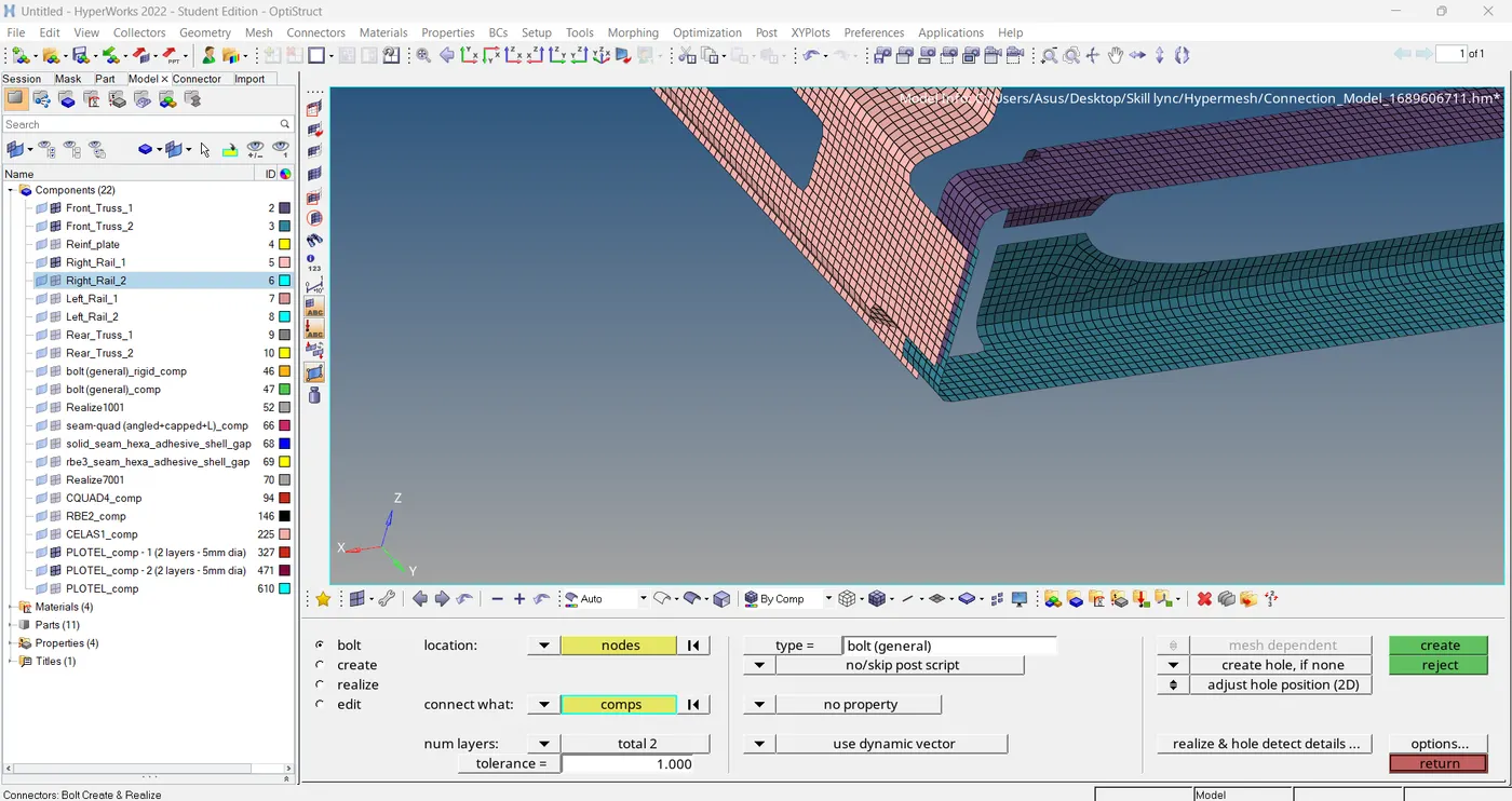
- The two components are joined by first selecting the 'Connectors' option in the 1D window and selecting the 'bolt' option which opens up a window for entering the further specifications. The type of bolt required is selected in the type window (bolt (general)).
- The nodes and components are selected where the attachment to be done. The tolerance between the components, and the specification of the connection like number of layers is provided and the create button is clicked. 'Create hole, if none' option is selected to create a hole for the bolt connection, if the component doesn't have pre-existing holes.
- The connection obtained is shown in the figure below.
Step 6 : Rear_truss_2 & Left_Rail_2:- Bolt Connector
- The two components are joined by first selecting the 'Connectors' option in the 1D window and selecting the 'bolt' option which opens up a window for entering the further specifications. The type of bolt required is selected in the type window (bolt (general)).
- The nodes and components are selected where the attachment to be done. The tolerance between the components, and the specification of the connection like number of layers is provided and the create button is clicked. 'Create hole, if none' option is selected to create a hole for the bolt connection, if the component doesn't have pre-existing holes.
- The connection obtained is same as the above figure.
Step 7 : Right_Rail_1 & Right_Rail_2:- Spot-weld with Rigid Elements
- The two components are joined by first selecting the 'Connectors' option in the 2D window and selecting the 'Spot' option which opens up a window for entering the further specifications. The type of Spot weld joining required is selected in the type window (Rigid).
- The nodes and components are selected where the attachment to be done. The tolerance between the components, and the specification of the connection like number of layers and Diameter of the weld is provided and the create button is clicked.
- The connection obtained is shown in the figure below.
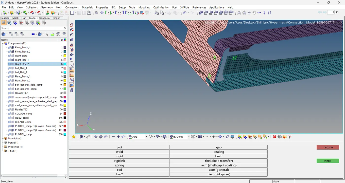
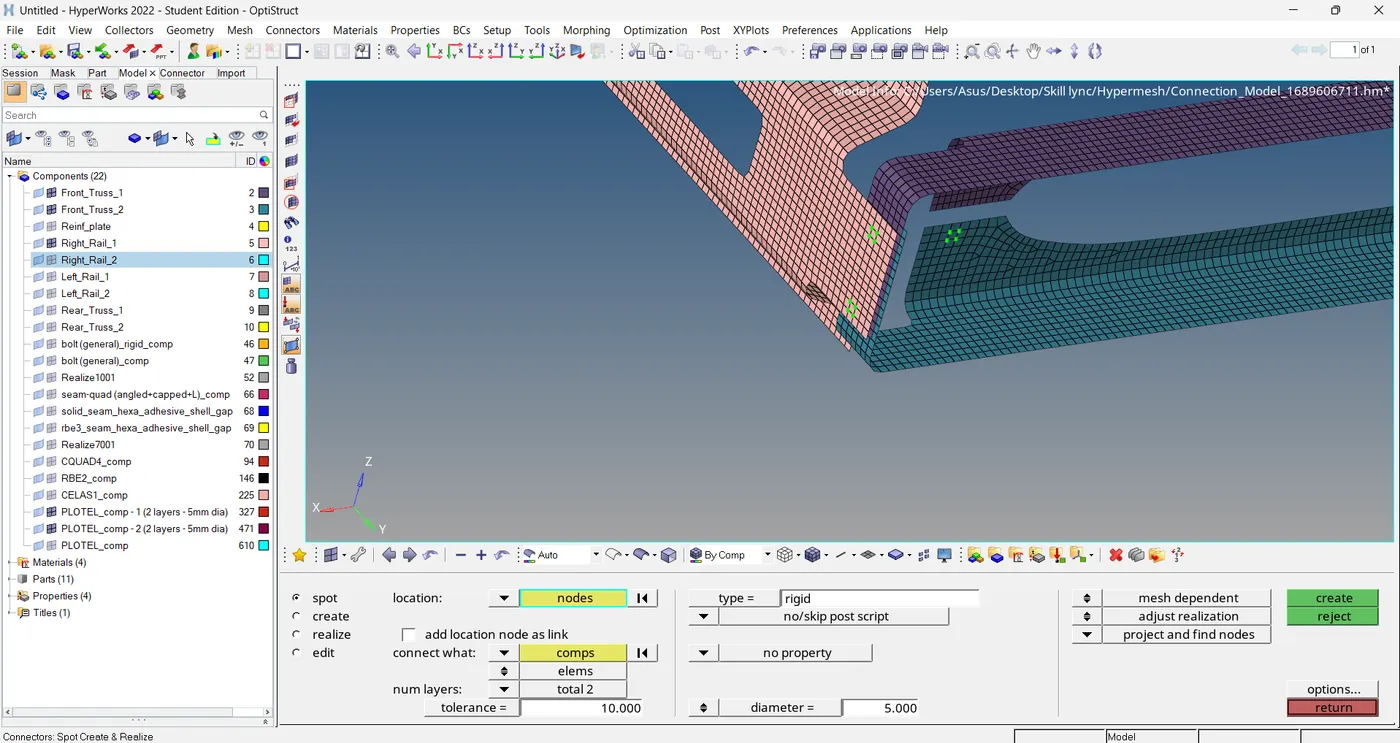
Step 7 : Right_Rail_1 & Right_Rail_2:- Spot-weld with Rigid Elements
- The two components are joined by first selecting the 'Connectors' option in the 2D window and selecting the 'Spot' option which opens up a window for entering the further specifications. The type of Spot weld joining required is selected in the type window (Rigid).
- The nodes and components are selected where the attachment to be done. The tolerance between the components, and the specification of the connection like number of layers and Diameter of the weld is provided and the create button is clicked.
- The connection obtained is shown in the figure below.
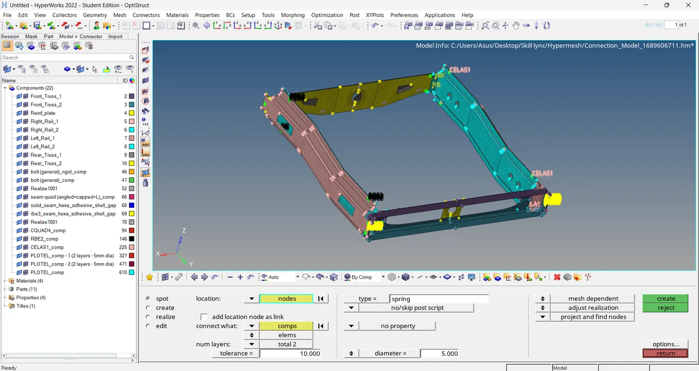
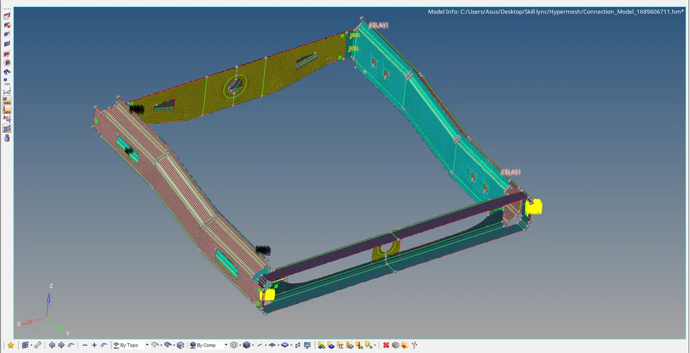
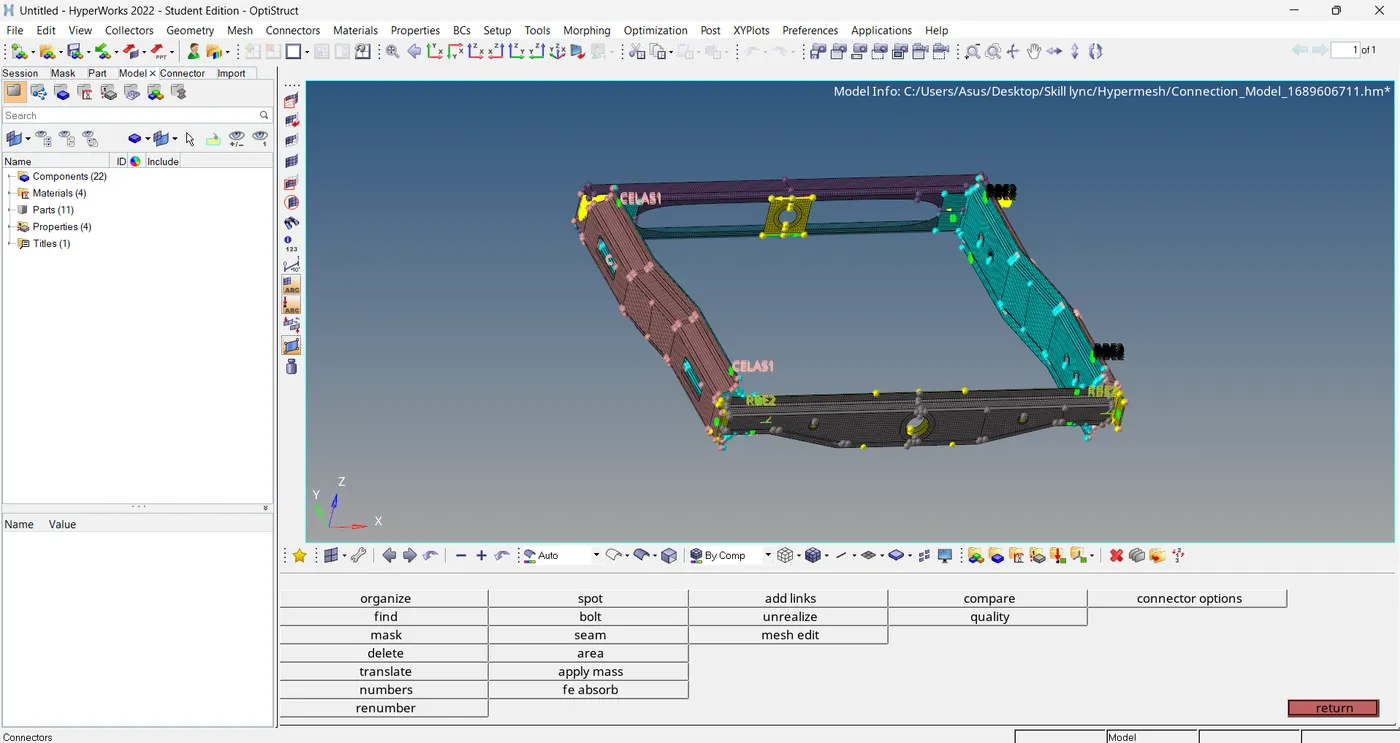
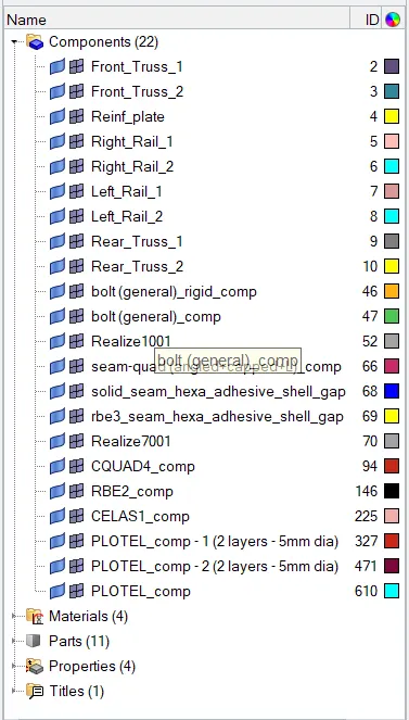
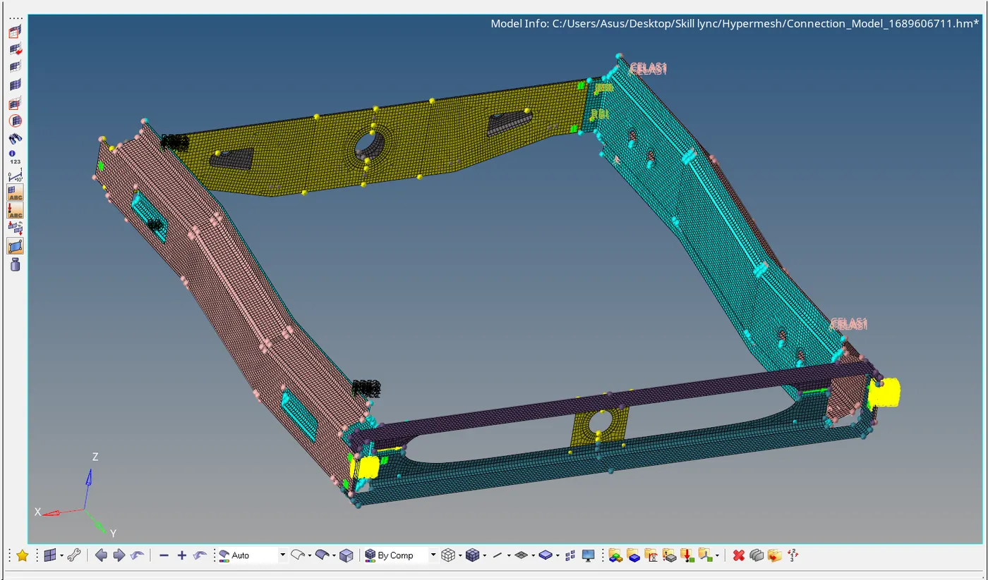
- The final model with all the required connections made is shown in the figure below.
Reference Links :
https://drive.google.com/file/d/1p_JSEMlAvWJXrTahQK5Bfw9mpoQ7cF0z/view?usp=sharing
https://drive.google.com/file/d/1uJZtB_WvbQbWiMXcCmXsDC0rbEA8r7cm/view?usp=sharing