Week-6 : Turbocharger Modelling
Aim: Exploring the Turbocharger
Types of Turbochargers :
1. Listing down the different turbochargers and locate examples from GT Power
- Variable Geometry Turbocharger - Examples->Diesle_VGT_EGR.gtm
- Waste Gate Turbocharger - Examples->Diesel_WGController.gtm
- Twin Scroll Turbocharger - Tutorials ->Turbo_Step5-final.gtm
- Two-stage Turbocharger - No example
- Electric Turbocharger - No example
- Twin Turbocharger -Examples ->Locomotive-Diesel-4stroke-v16.gtm
2. Exploring tutorial 6 and 7
2.1 Tutorial 6
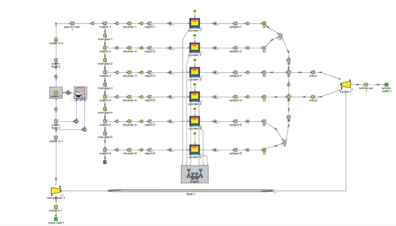
Engine Layout with the final step of tutorial 6
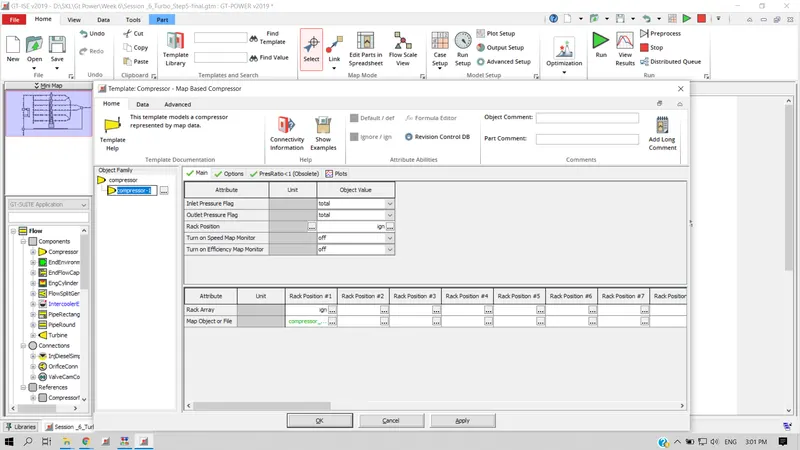
Compressor and Turbine Settings :
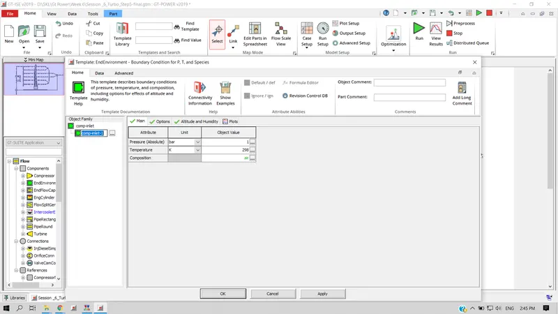
Inlet pressure and temperature can be varied based on the test settings.
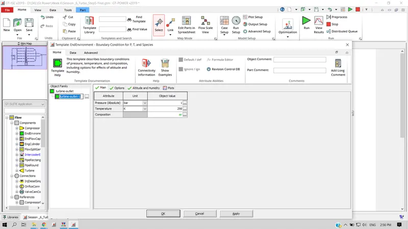
Inlet boundary conditions can be varied with Pressure and Temperature. It is also possible to set the altitude and humidity for comprehending the engine performance for various regions.
Rack position setting for compressor and turbine
Turbine Map Settings
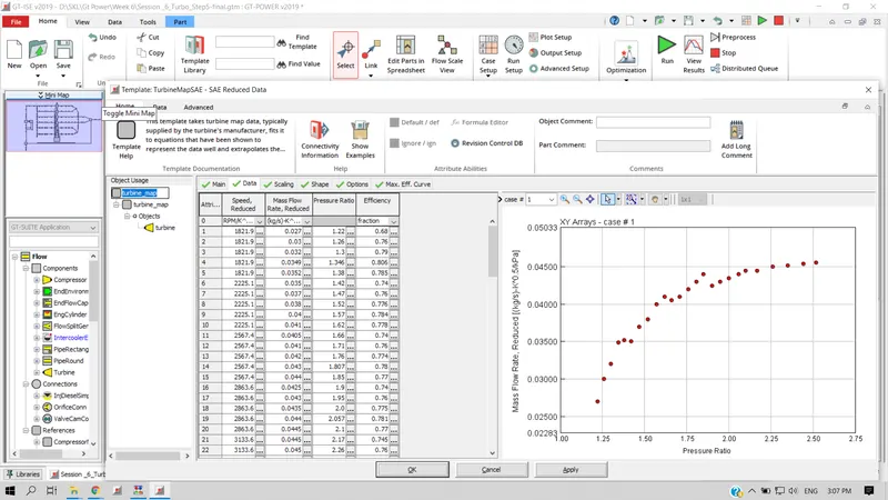
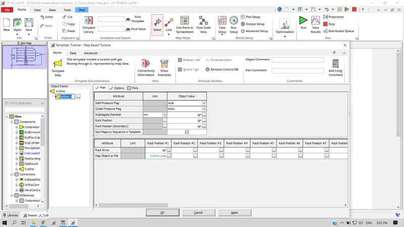
Rack position can be set by filling the rack position array or most of the times the data is taken from the turbo manufacturer.
Plotting Operating points :
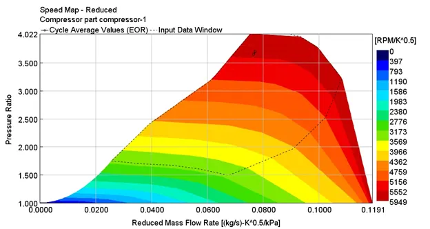
Compressor map
Turbine map
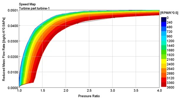
The dots on the compressor and turbine map indicates the operating point.
Performance:

The above matrix depicts the engine performance at two different altitudes. First being at sea level and second at 5000m. As it is known the power engine does depend on the breathing of the engine i.e amount of air sucked into the cylinder. At higher altitudes, the density of air and atmospheric pressure reduces by influencing the performance of the engine. It is quite visible(2nd column) that at higher altitudes the power has gone down and so is the airflow rate.
2.2 In which application Variable Geometry Turbine is beneficial?
- High A/F ratio and high peak torque at low engine speed
- Prevent over-boosting at high engine speed
- reduce exhaust gas emissions and improve the fuel economy
- Improve response time of the turbocharger during transient engine operation
3. Explore example - Diesel VGT EGR and understand the modelling part
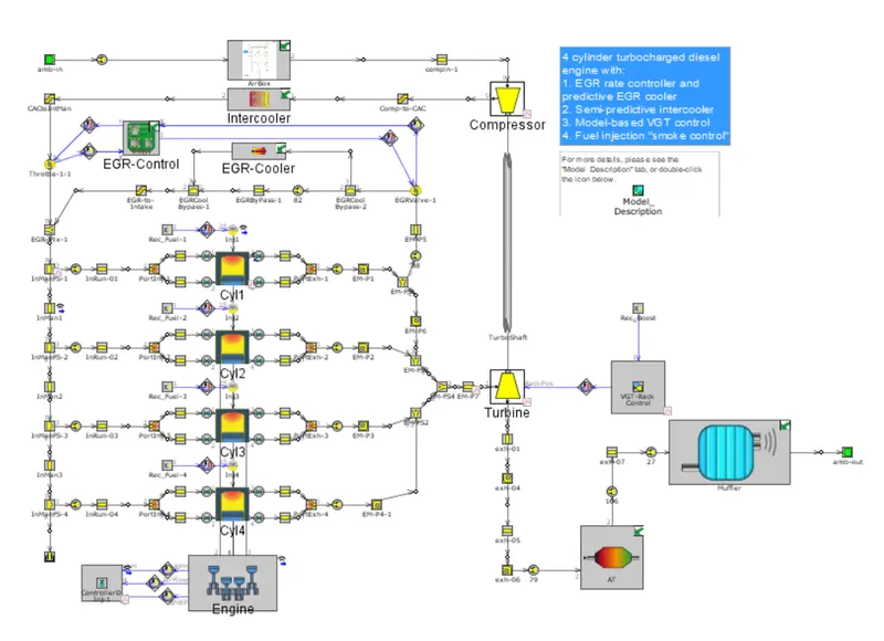
The above model is very complex. Some of the crucial components of the parts will be explained below and which needs keen attention while modelling the turbocharger.
a. Intercooler
The intercooler function is to cool the incoming air from the compressor before it enters into the next stage of compression. Cooling the air leads to increase the density of the air thereby making it even more feasible for incylinder air compression.
b. Varible geometry turbocharger
VGT concept dates by 50s, since then various designs have been appeared. The two more common ones are pivoting vane and moving wall type. Compared to fixed geometry , VGT allows significant flexibility over the pressure ratio flow across the turbine by varying extension area. This plays vital role in improving low speed torque , reducing turbo lag in diesel engines and driving EGR flow .
c. Rack positon controller
It basically controls the movement of vanes of the turbine. At lower speed , amount of exhaust gases is low , so vanes are kept minimum position inorder to increase the gas velocity and reduce turbo lag. At higher speed vanes will be kept at max position so as to increase the boost. Rack position is also connected to intake manifold to check the requirement of air for the engine.
d. EGR Controller
EGR controller is used to dilute the air mixture to lower incylinder temperature which eventually lowers the NOx formation. As it is known formation of NOx is directly related to the high temperature developed in the cylinder.