Week-6 : Turbocharger Modelling
Aim:
Turbocharger modelling using GT-Suite.
Objective:
- List down different TC and locate examples from GT Power.
- Explore tutorial number 6 and 7.
- Plot operating points on compressor and turbine map.
- In which application geometry turbine is beneficial?
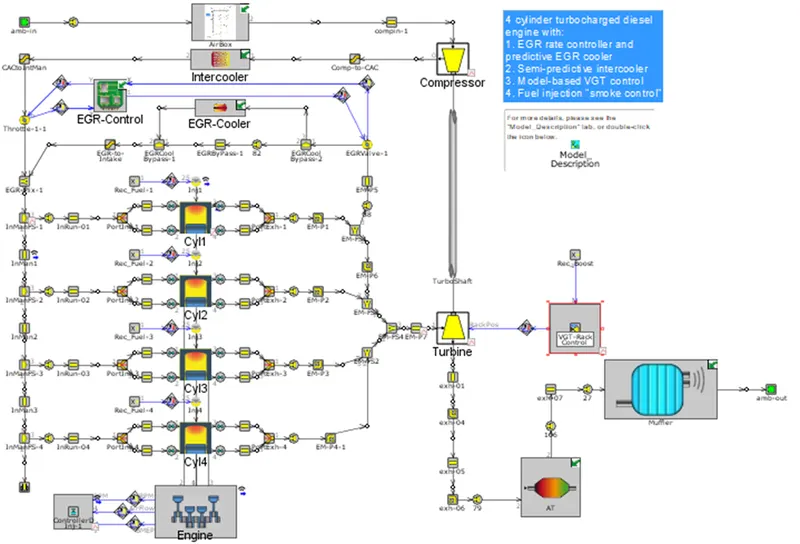
- Explore example – diesel VGT EGR and understand the modelling part.
Theory:
Turbocharger:
A turbocharger (technically a turbocharger), colloquially known as turbo, is a turbine-driven, forced – induction device that increases an internal combustion engine power output by forcing extra compressed air into the combustion chamber. This improvement over a naturally aspirated engine power output is because the compressor can force more air—and proportionately more fuel—into the combustion chamber than atmospheric pressure.
In naturally aspirated piston engines, intake gases are drawn or "pushed" into the engine by atmospheric pressure filling the volumetric void caused by the downward stroke of the piston (which creates a low-pressure area), similar to drawing liquid using a syringe. The amount of air actually drawn in, compared with the theoretical amount if the engine could maintain atmospheric pressure, is called volumetric efficiency. The objective of a turbocharger is to improve an engine's volumetric efficiency by increasing density of the intake gas (usually air) allowing more power per engine cycle.
The turbocharger's compressor draws in ambient air and compresses it before it enters into the intake manifold at increased pressure. This results in a greater mass of air entering the cylinders on each intake stroke. The power needed to spin the centrifugal compressor is derived from the kinetic energy of the engine's exhaust gases.
In automotive applications, 'boost' refers to the amount by which intake manifold pressure exceeds atmospheric pressure at sea level. This is representative of the extra air pressure that is achieved over what would be achieved without the forced induction. The level of boost may be shown on a pressure gauge, usually in bar, psi or possibly kPa. The control of turbocharger boost has changed dramatically over the 100-plus years of their use. Modern turbochargers can use waste gates, blow-off valves and variable geometry.
Types of turbocharger:
- Single turbo
- Twin turbo
- Variable geometry turbo
- Variable twin scroll turbo
- Electric turbo.
Single turbo:
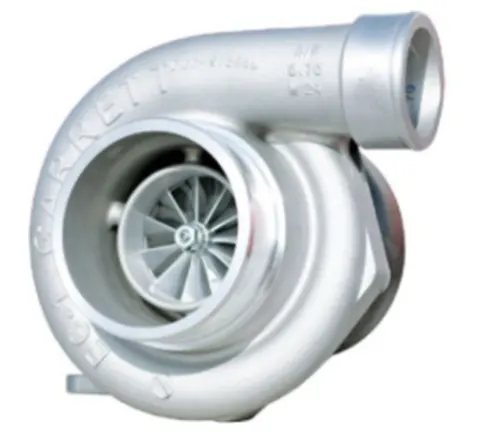
Single turbochargers alone have limitless variability. Differing the compressor wheel size and turbine will lead to completely different torque characteristics. Large turbos will bring on high top-end power, but smaller turbos will provide better low-end grunt as they spool faster. There are also ball bearing and journal bearing single turbos. Ball bearings provide less friction for the compressor and turbine to spin on, thus are faster to spool (while adding cost).
Advantages:
- Cost effective way of increasing an engine’s power and efficiency.
- Simple, generally the easiest of the turbocharging options to install.
- Allows for using smaller engines to produce the same power as larger naturally-aspirated engines, which can often remove weight.
Disadvantages:
- Single turbos tend to have a fairly narrow effective RPM range. This makes sizing an issue, as you’ll have to choose between good low-end torque or better high-end power.
- Turbo response may not be as quick as alternative turbo setups.
Twin scroll turbo:
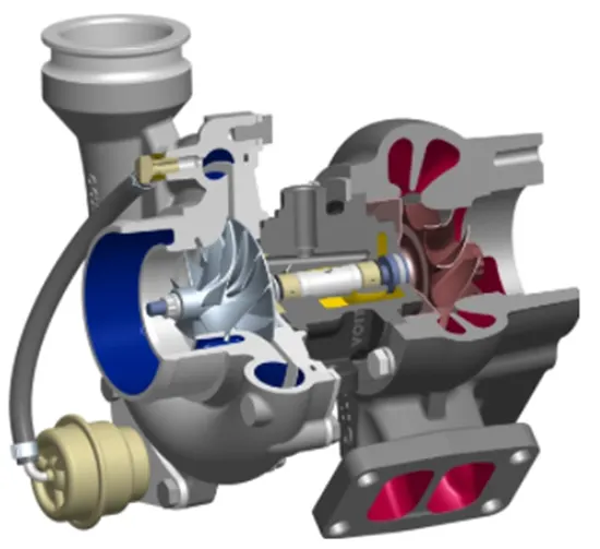
Twin-scroll turbochargers are better in nearly every way than single-scroll turbos. By using two scrolls, the exhaust pulses are divided. For example, on four cylinder engines (firing order 1-3-4-2), cylinders 1 and 4 might feed to one scroll of the turbo, while cylinders 2 and 3 feed to a separate scroll. Why is this beneficial? Let’s say cylinder 1 is ending its power stroke as the piston approaches bottom dead centre, and the exhaust valve starts to open. While this is happening, cylinder 2 is ending the exhaust stroke, closing the exhaust valve and opening the intake valve, but there is some overlap. In a traditional single-scroll turbo manifold, the exhaust pressure from cylinder 1 will interfere with cylinder 2 pulling in fresh air since both exhaust valves are temporarily open, reducing how much pressure reaches the turbo and interfering with how much air cylinder 2 pulls in. By dividing the scrolls, this problem is eliminated.
Advantages:
- More energy is sent to the exhaust turbine, meaning more power.
- A wider RPM range of effective boost is possible based on the different scroll designs.
- More valve overlap is possible without hampering exhaust scavenging, meaning more tuning flexibility.
Disadvantages:
- Requires a specific engine layout and exhaust design (eg: I4 and V8 where 2 cylinders can be fed to each scroll of the turbo, at even intervals).
- Cost and complexity versus traditional single turbo.
Variable geometry turbocharger (VGT):
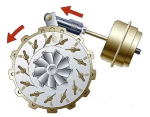
Perhaps one of the most exceptional forms of turbocharging, VGTs are limited in production (though fairly common in diesel engines) as a result of cost and exotic material requirements. Internal vanes within the turbocharger alter the area-to-radius (A/R) ratio to match the RPM. At low RPM, a low A/R ratio is used to increase exhaust gas velocity and quickly spool up the turbocharger. As the revs climb, the A/R ratio increases to allow for increased airflow. The result is low turbo lag, a low boost threshold, and a wide and smooth torque band.
Advantages:
- Wide, flat torque curve. Effective turbocharging at a very wide RPM range.
- Requires just a single turbo, simplifying a sequential turbo setup into something more compact.
Disadvantages:
- Typically only used in diesel applications where exhaust gases are lower so the vanes will not be damaged by heat.
- For gasoline applications, cost typically keeps them out as exotic metals have to be used in order to maintain reliability. The tech has been used on the Porsche 997, though very few VGT gasoline engines exist as a result of the cost associated.
Variable twin scroll turbocharger:
It combines the advantages of a twin scroll turbo and a variable geometry turbo. It does this by the use of a valve which can redirect the exhaust airflow to just a single scroll, or by varying the amount the valve opens can allows for the exhaust gases to split to both scrolls. The VTS turbocharger design provides a cheaper and more robust alternative to VGT turbos, it means it is a viable option for petrol engine applications. It allows for a wide flat torque curve. It is more robust in design versus a VGT, depending on the material selection.
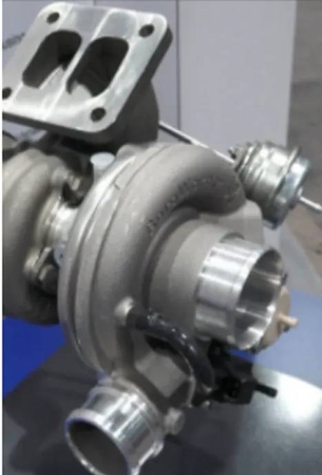
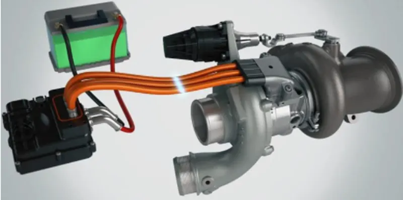
Electric turbocharger:
Aeristech’s patented Full Electric Turbocharger Technology is a new enabling technology that will help vehicle manufacturers meet stringent future emissions legislation whilst providing excellent response throughout the engine operating range, even at low engine rpm and vehicle speed.FETT is the ultimate solution for extreme engine downsizing and improved engine efficiency using a single stage turbocharger.
Throwing a powerful electric motor in the mix eliminates nearly all of the drawbacks of a turbocharger. Turbo lag? Gone. Not enough exhaust gases? No problem. Turbo can’t produce low-end torque? Now it can! Perhaps the next phase of modern turbocharging, there are undoubtably drawbacks of the electric path as well.
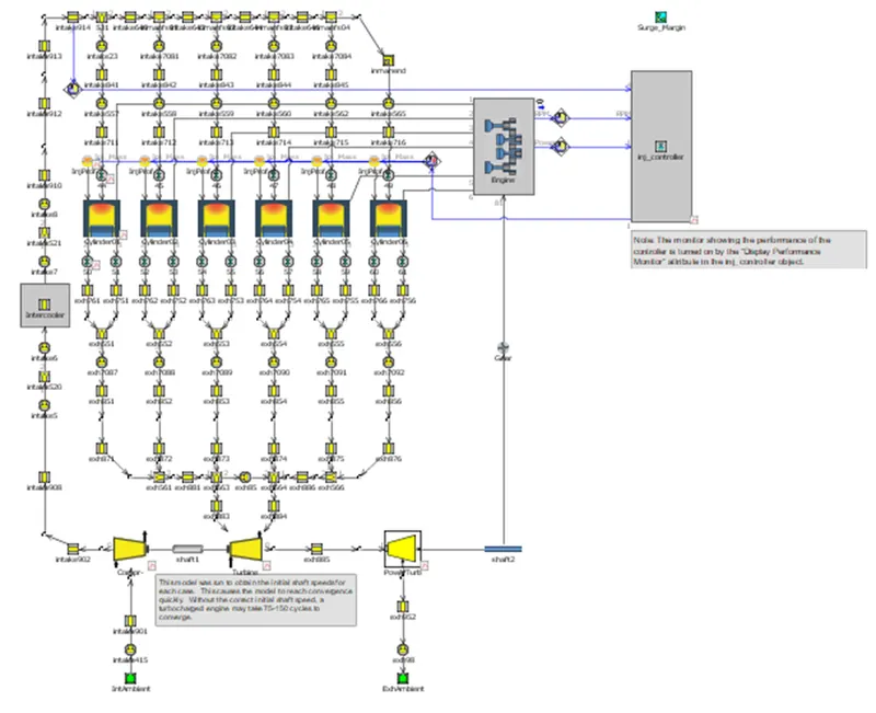
GT Power examples:
Normal turbocharger model:
VGT:
Waste Gate model:
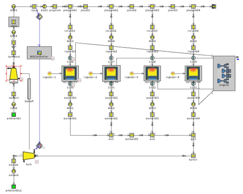
Tutorials 7:
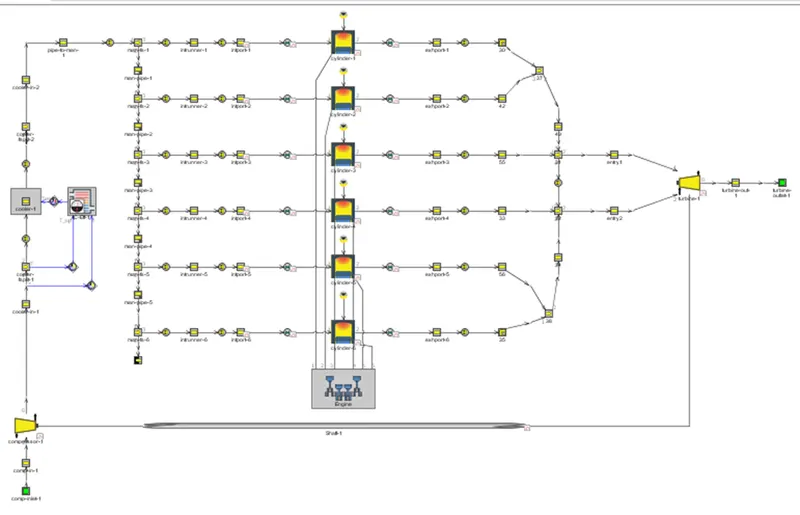
VGT simulation:
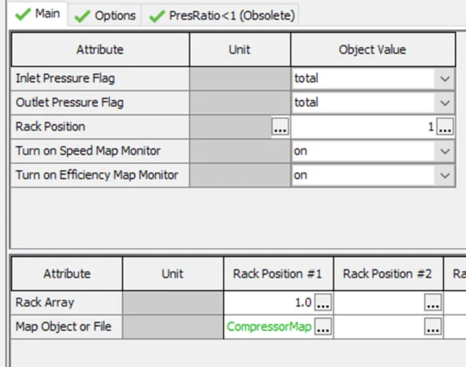
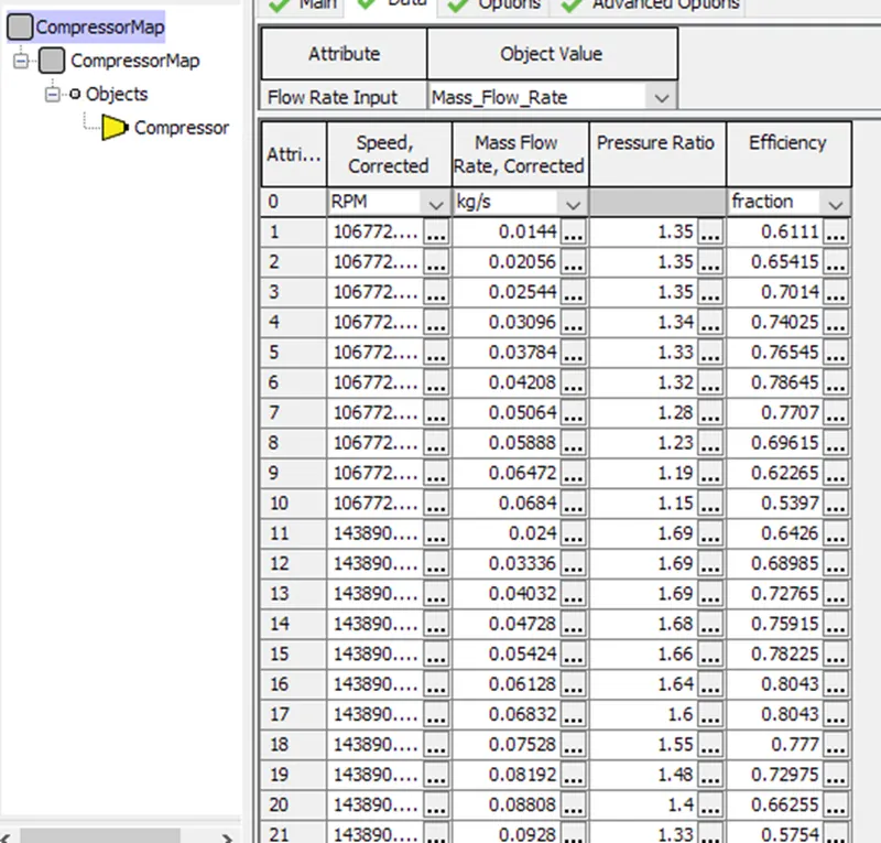
Compressor:
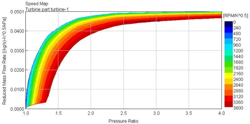
Turbine:
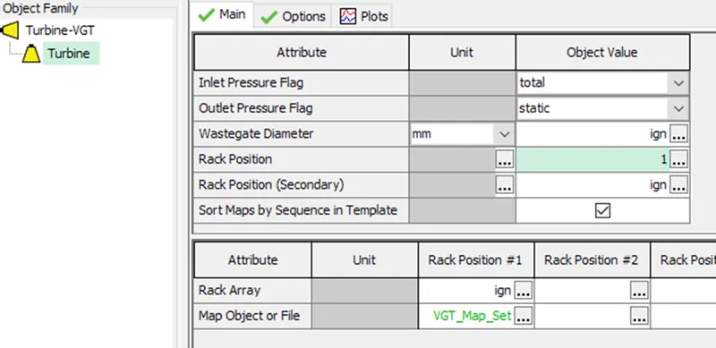
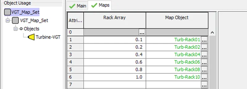
Case study:
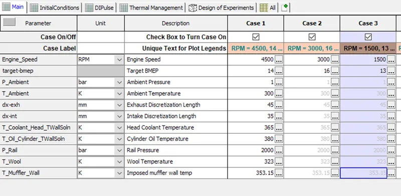
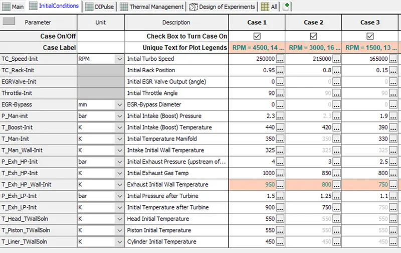
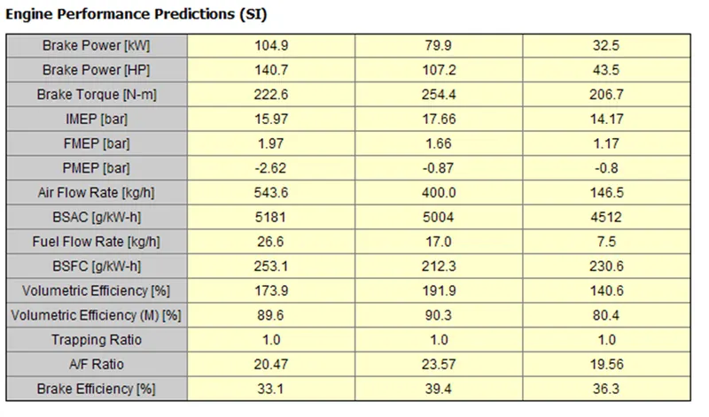
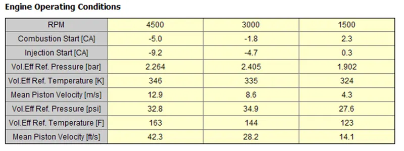
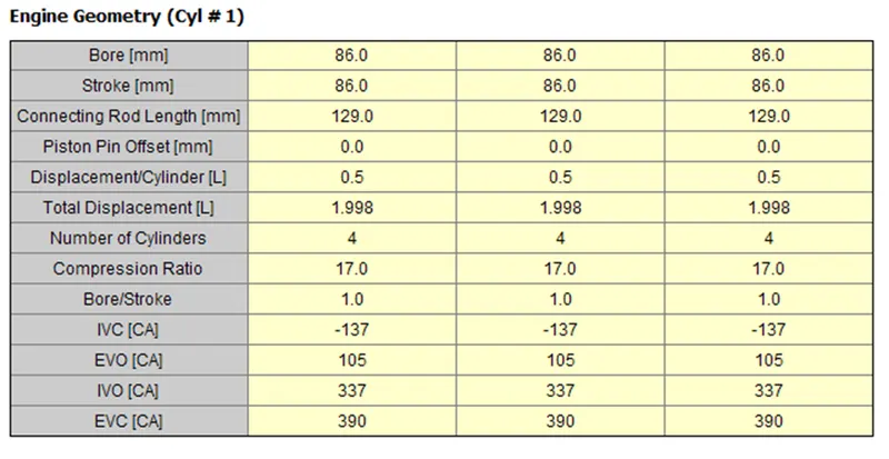
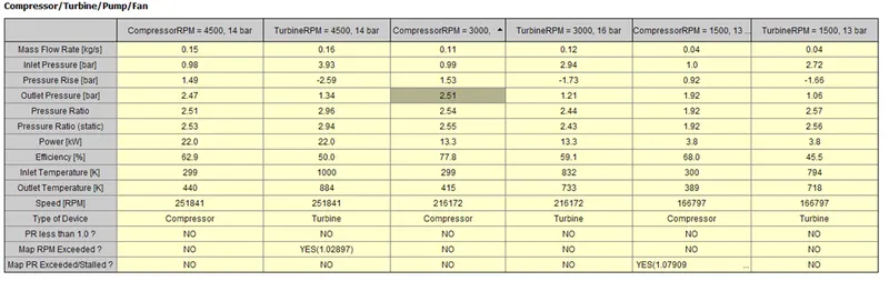
Results:
|
4500rpm |
3000rpm |
1500rpm |
|
|
NOx in ppm |
222.5 |
449.22 |
409.68 |
|
Volumetric efficiency (m) |
92.6 |
90.4 |
80.7 |
|
BMEP |
14 |
16 |
13 |
|
Exhaust temperature |
1093 |
905 |
912 |
Compressor map:
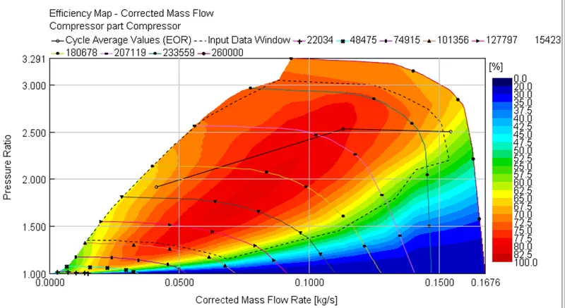
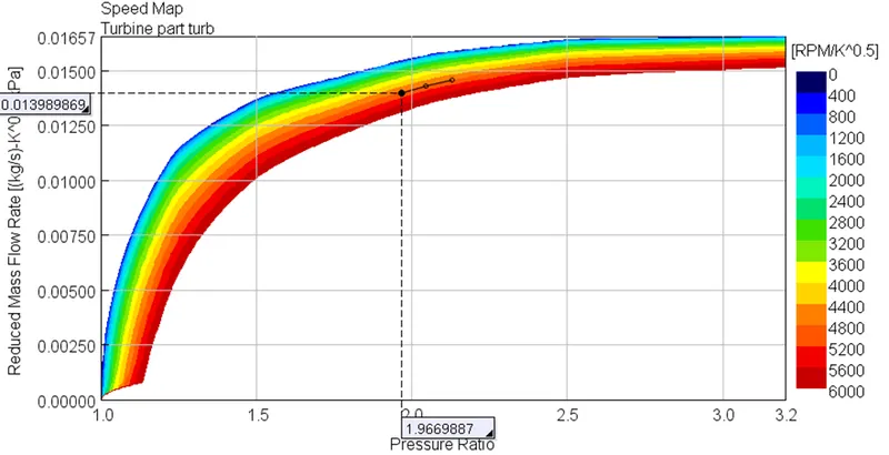
Turbine map:
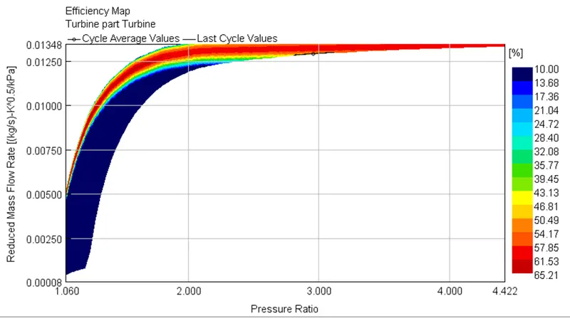
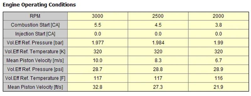
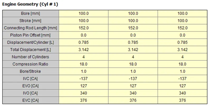
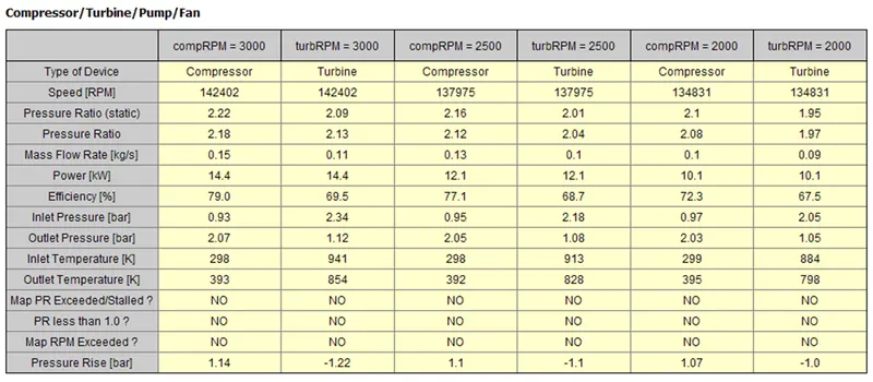
Waste gate turbocharger simulation:
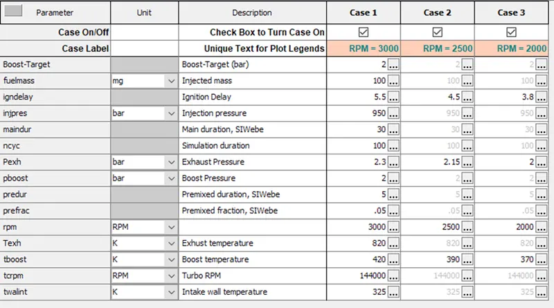
Case study:
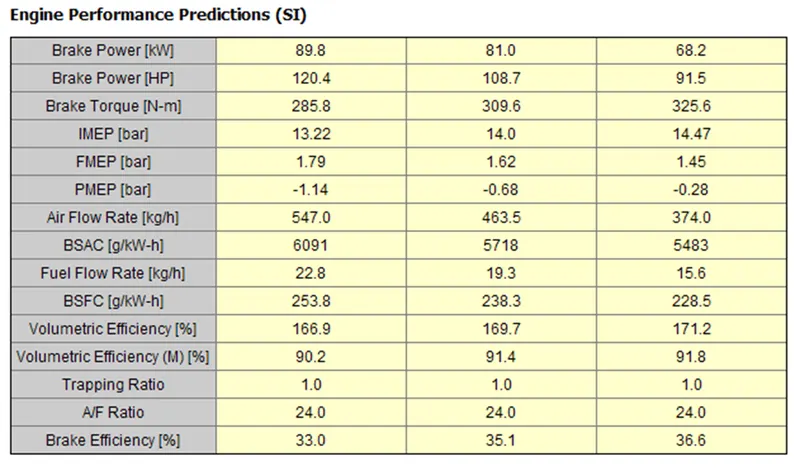
Results:
|
3000rpm |
2500rpm |
2000rpm |
|
|
Maximum pressure |
107.23 |
107.31 |
106.45 |
|
Volumetric efficiency (m) |
90 |
91.7 |
91.9 |
|
BMEP |
11.4 |
12.4 |
13 |
|
Exhaust temperature |
994 |
965 |
935 |
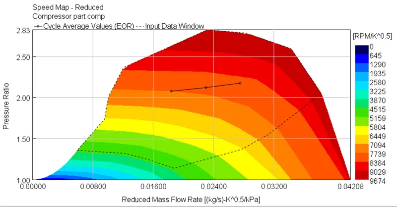
Compressor map:
Turbine map:
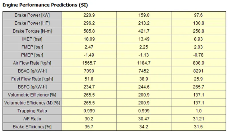
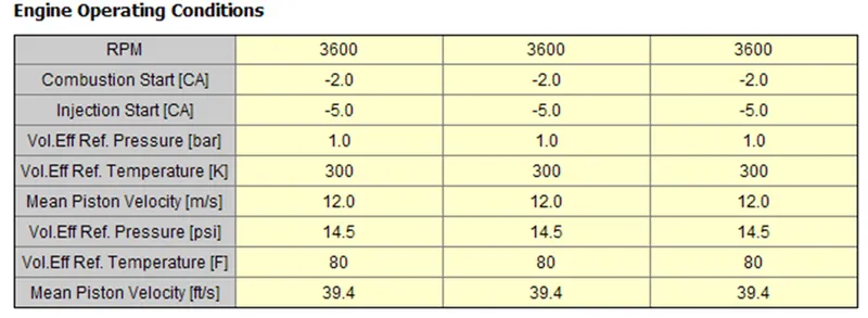
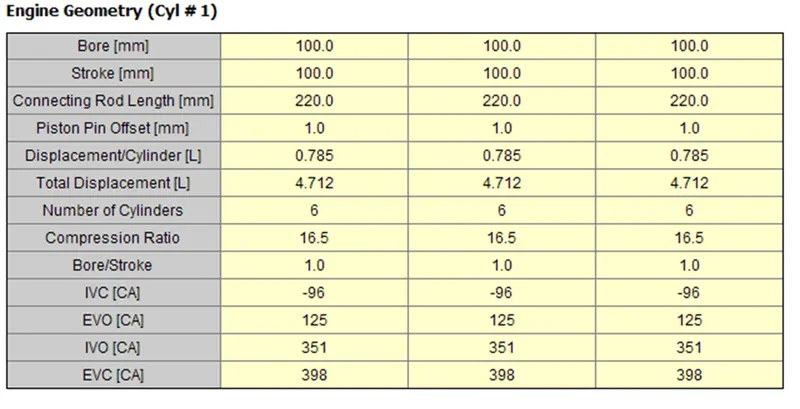
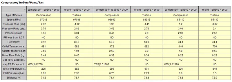
Tutorials 7 simulation:
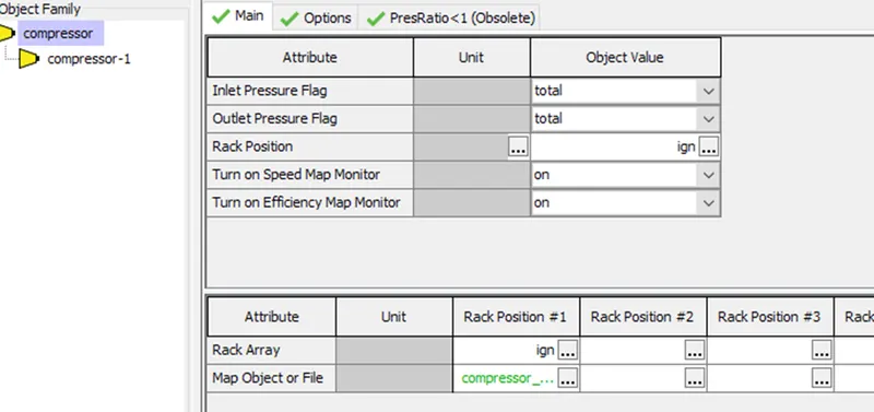
Compressor details:
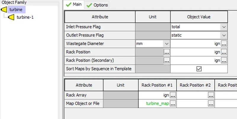
Turbine details:
Case study:
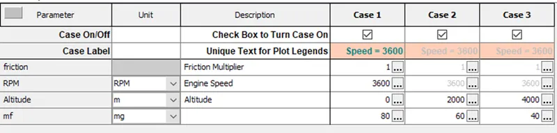
Results:
|
Altitude/fuel |
0/80 |
2000/60 |
4000/40 |
|
Maximum pressure |
171.23 |
126.91 |
84.21 |
|
Volumetric efficiency (m) |
264.6 |
200.1 |
136.6 |
|
BMEP |
15.6 |
11.2 |
6.9 |
|
Exhaust temperature |
847 |
840 |
831 |
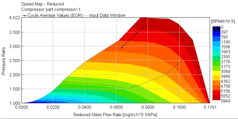
Compressor map:
Turbine map: