Turbocharger Modelling in GT POWER
Aim:
Turbocharger Modelling using GT POWER
Objective:
- List down different TC and locate examples from GT Power
- Explore tutorial number 6 and 7
- Plot operating points on compressor and turbine maps
- In which application Variable Geometry Turbine is beneficial?
- Explore example- Diesel VGT EGR and understand the modeling part
Theory:
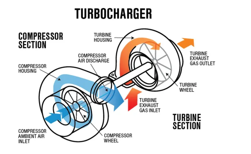
A turbocharger, colloquially known as a turbo, is a turbine-driven, forced induction device that increases an internal combustion engine's power output by forcing extra compressed air into the combustion chamber. This improvement over a naturally aspirated engine's power output is because the compressor can force more air—and proportionately more fuel—into the combustion chamber than atmospheric pressure (and for that matter, ram air intakes) alone.
Wastegate turbocharger
Nowadays, vehicles with turbocharged engines feature the wastegate turbocharger. This technology helps to deliver optimum engine performance during peak operating conditions. In addition, the wastegate valve prevents the turbocharger from over-running. Particularly, it also avoids the engine from over-boost and prevents any mechanical failure.
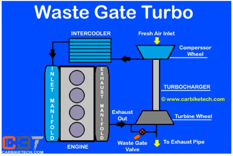
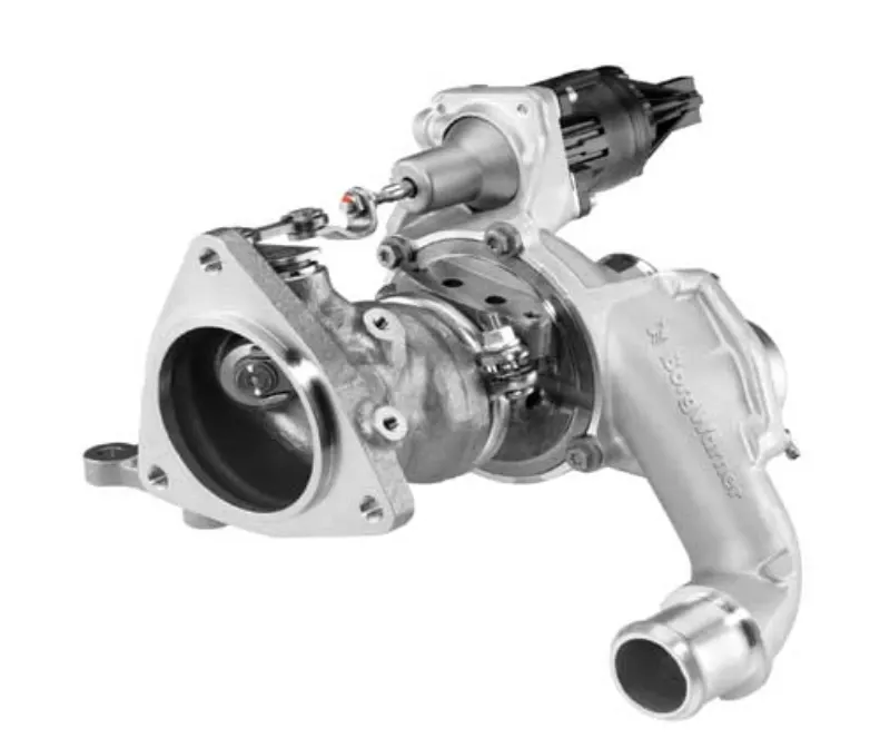
This feature in the turbocharger consists of a bypass valve. It circumvents some part of the exhaust gas going to the turbine and releases them into the outlet. Furthermore, the waste-gate turbocharger has a bypass valve built into the turbine housing. It diverts some of the exhaust gases away from the turbine wheel through this valve.
Advantages of wastegate turbocharger:
Besides, the waste-gate system has many advantages which include the following:
- Needs a smaller space to fit.
- Reduces turbo lag to some extent.
- Installation of compact and simple external exhaust pipe system. Thus, reducing the engine weight.
- Delivers optimum engine performance at all times.
- Avoids mechanical damage to engine parts.
Variable-geometry turbochargers (VGTs)
Variable-geometry turbochargers (VGTs), occasionally known as variable-nozzle turbines (VNTs), are a type of turbochargers, usually designed to allow the effective aspect ratio of the turbocharger to be altered as conditions change. This is done because the optimum aspect ratio at low engine speeds is very different from that at high engine speeds.
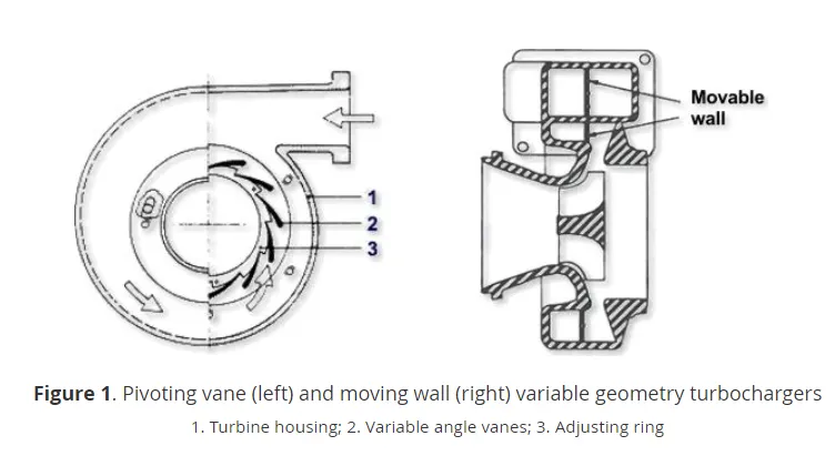
If the aspect ratio is too large, the turbo will fail to create boost at low speeds; if the aspect ratio is too small, the turbo will choke the engine at high speeds, leading to high exhaust manifold pressures, high pumping losses, and ultimately lower power output. By altering the geometry of the turbine housing as the engine accelerates, the turbo's aspect ratio can be maintained at its optimum. Because of this, VGTs have a minimal amount of lag, a low boost threshold, and high efficiency at higher engine speeds.
VGTs tend to be much more common on diesel engines, as lower exhaust temperatures mean they are less prone to failure. Early gasoline-engine VGTs required significant pre-charge cooling to extend the turbocharger life to reasonable levels, but advances in technology have improved their resistance to high-temperature gasoline exhaust, and they have started to appear increasingly in gasoline-engine cars.
Twin-turbo
Twin-turbo or bi-turbo designs have two separate turbochargers operating in either a sequence or in parallel. In a parallel configuration, both turbochargers are fed one-half of the engine's exhaust. In a sequential setup one turbocharger runs at low speeds and the second turns on at a predetermined engine speed or load. Sequential turbochargers further reduce turbo lag, but require an intricate set of pipes to properly feed both turbochargers.
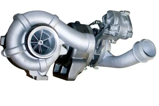
Two-stage variable twin-turbos employ a small turbocharger at low speeds and a large one at higher speeds. They are connected in a series so that boost pressure from one turbocharger is multiplied by another, hence the name "2-stage." The distribution of exhaust gas is continuously variable, so the transition from using the small turbocharger to the large one can be done incrementally. Twin turbochargers are primarily used in Diesel engines.
Compressor map:
In selecting a turbocharger for a given application, a single turbocharger with a single compressor solution is the preferred choice for reasons of cost and complexity. With increased use of higher levels of high pressure EGR, especially in diesel engines, this can be particularly challenging. As shown in Figure 1, high levels of high pressure EGR can tax the limits of a single compressor solution [Krivitzky 2012]. Large fractions of high pressure EGR at low load/low speed reduces the mass flow through the turbocharger and pushes the demand for a compressor with a surge line far to the left. At high load/speed conditions where EGR fractions are relatively low, demand for high rated power requires a high pressure ratio at a high mass flow. As low load/speed EGR rates increase, the difference between these two extremes can increase and require very wide compressor map widths. While multiple compressors offer one solution to this problem, the potential savings in cost and complexity of using a single compressor provides strong motivation for considering options to expand the map width of a single compressor.
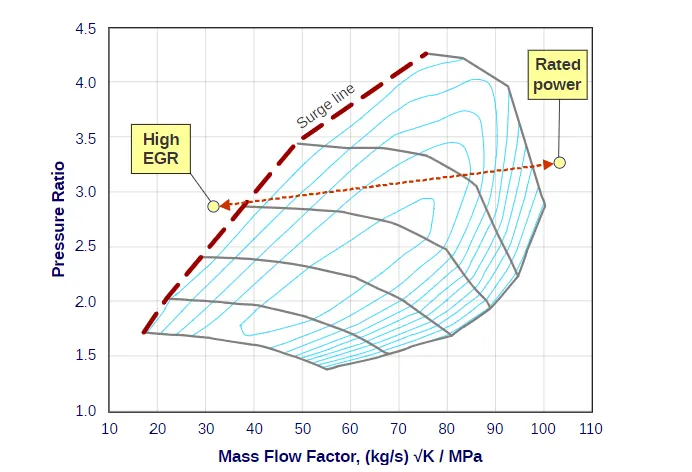
Figure 1. Critical Engine Points on Compressor Map
Compressor map wide enhancement is of course only useful if the turbine can provide sufficient power to the compressor to generate the required pressure and flow rate. In some cases, variable geometry turbines offer an expanded range needed to drive a compressor with an expanded map width.
Different turbocharger model available in GT POWER module
Single fixed geometry TC
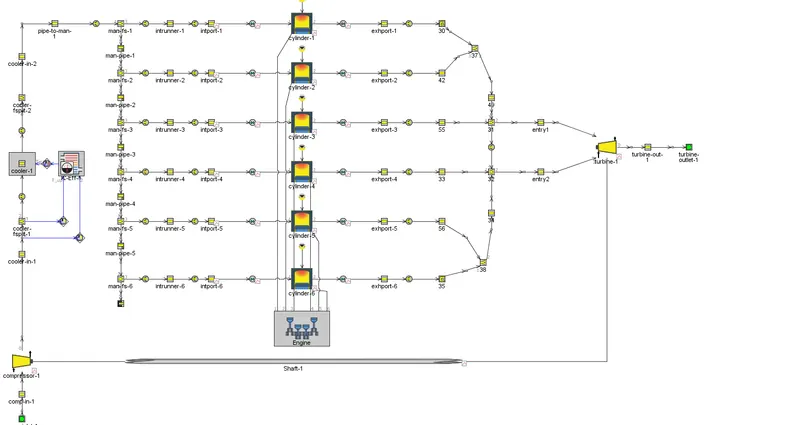
Variable geometry TC
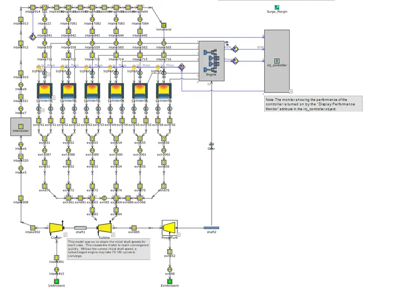
6 cylinder DI TC
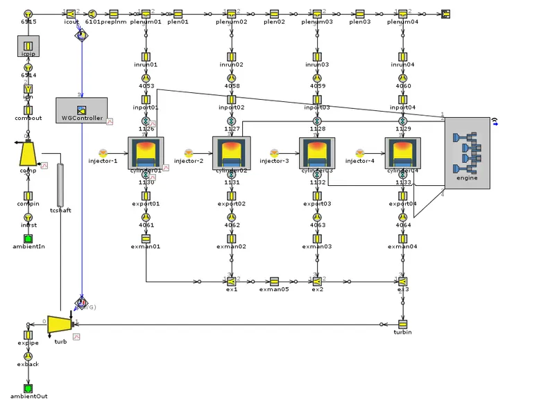
Waste gate controller TC
Exploring tutorial 6 and 7 to setup turbo charger model:
Simulation model:
6 cylinder fixed turbocharged model
Boundary conditions:
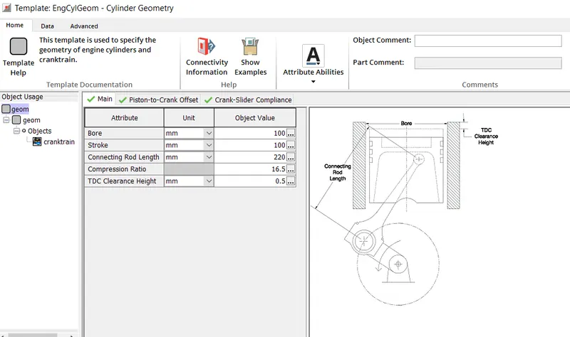
Engine boundary condition
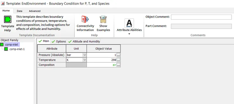
Inlet
Injection
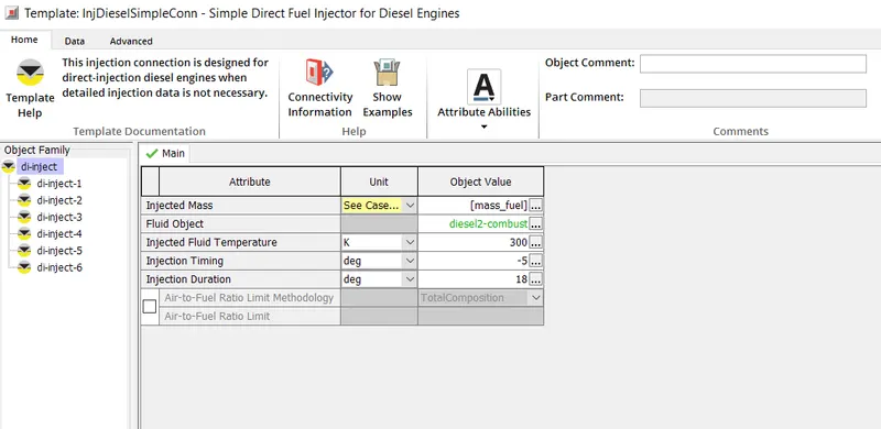
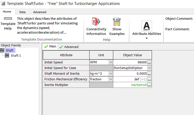
Shaft condition
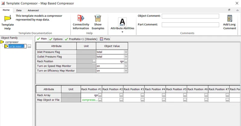
Compressor setup
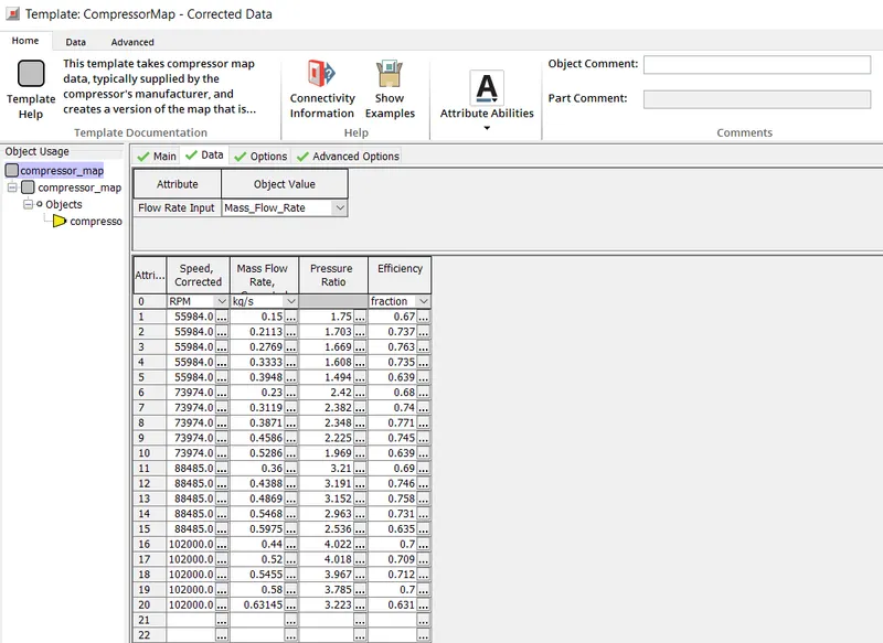
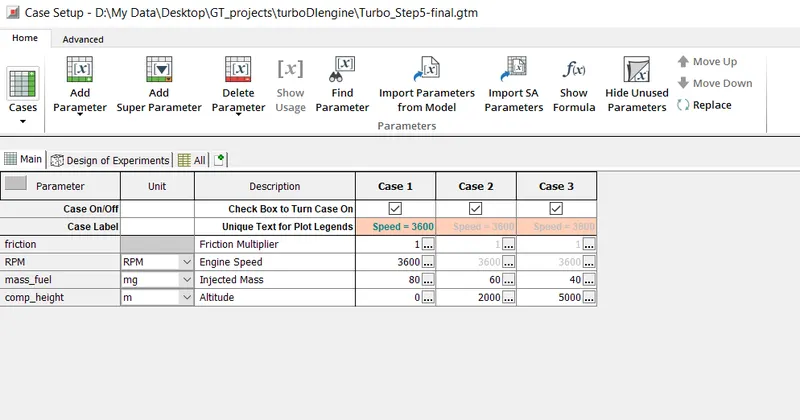
Case set up as a function of altitude and mass of fuel
GT POST
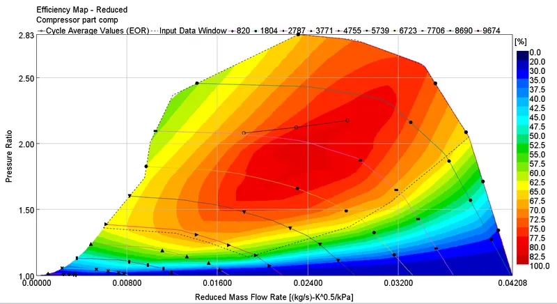
Efficiency of all cases in compressor map
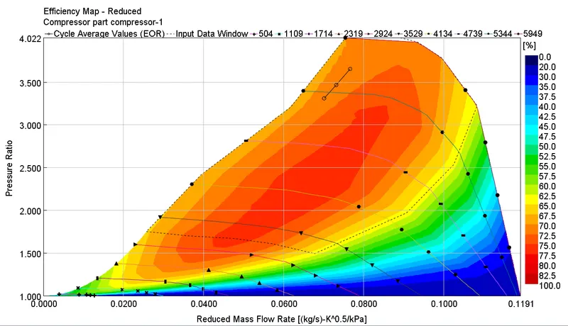
From the compressor map region, all the three points of cases remains almost in safe design domain. Failure of the engine is highly reduced with these applied boundary conditions.
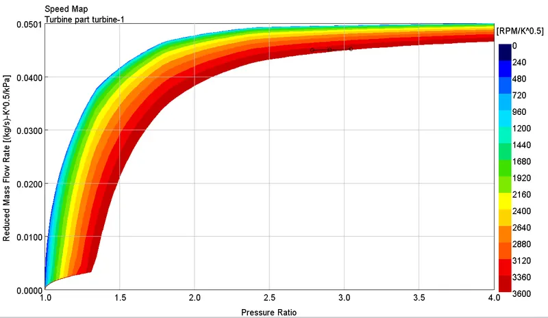
Efficiency of all cases in turbine map
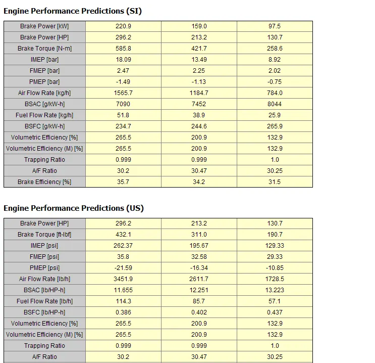
Engine performance output data
Compressor and turbine performance
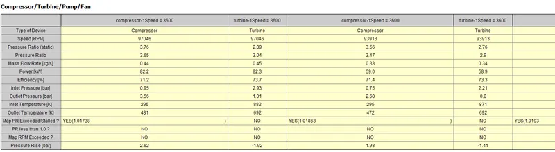
As altitude gets higher, air flow rate decreases so less amount of fuel is required to bun the fuel efficiently and therefore brake power decreases. The rpm and brake torque also decreases. So for hilly region, the speed of vehicle is less compared to vehicle running at plane land.
Waste gate turbocharger
Simulation model:
Boundary conditions:
Engine boundary condition
Inlet
Compressor setup
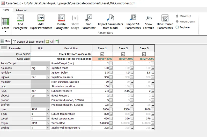
Case set up as a function of altitude and mass of fuel
GT POST:
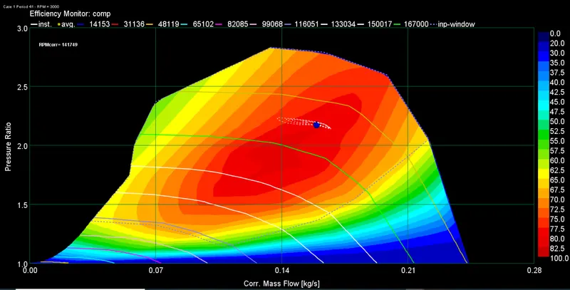
Efficiency of case 1 in compressor map
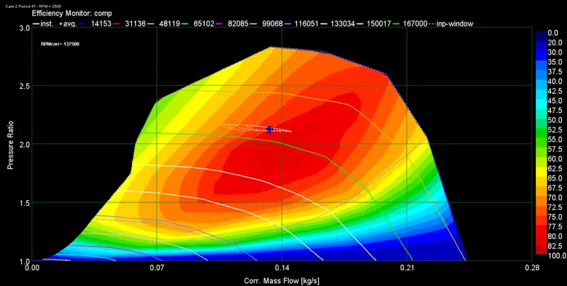
Efficiency of case 2 in compressor map
Efficiency of case 3 in compressor map
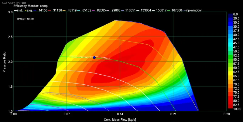
Combined cases in compressor map
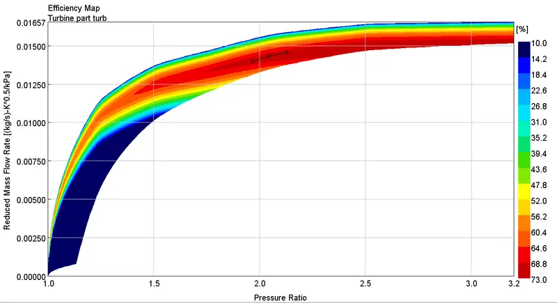
Turbine map
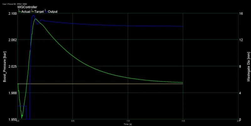
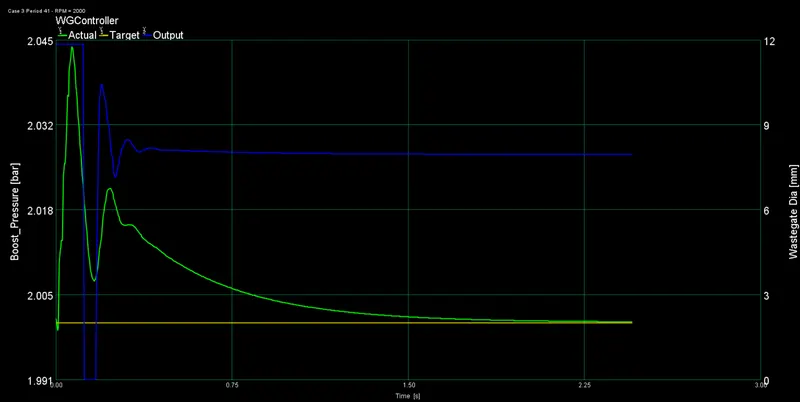
Waste gate opening case1
Waste gate opening case2
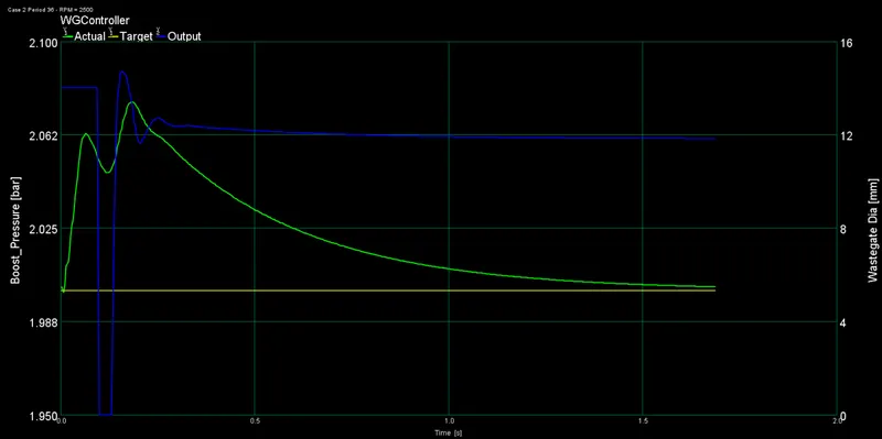
Waste gate opening case3
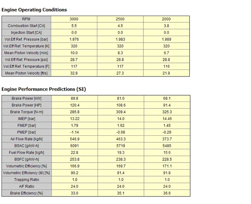
Engine performance output data
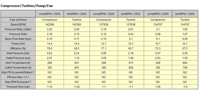
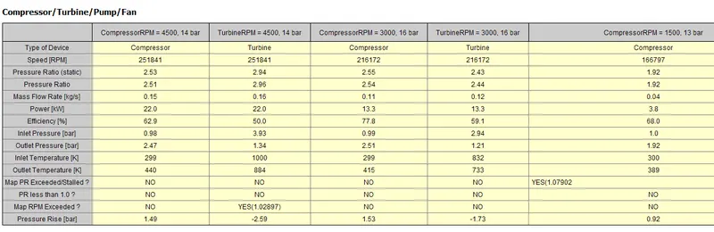
Compressor and turbine output data
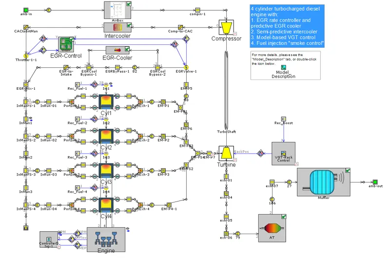
Variable geometry turbine turbocharger(VGT EGR MODEL)
Simulation model:
Simulation sub model:
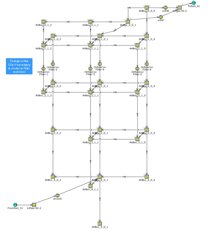
Airbox model
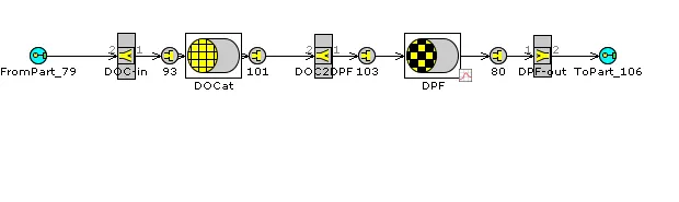
AT model
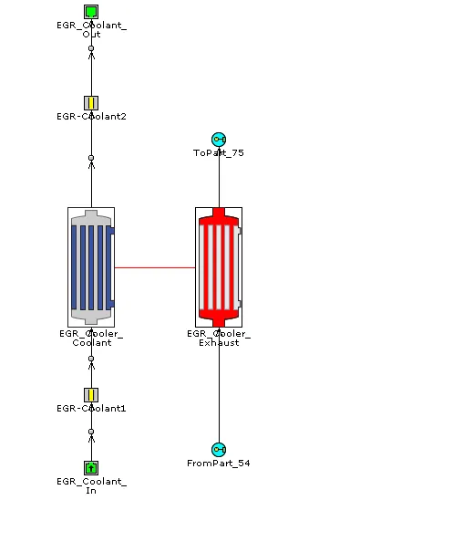
EGR model
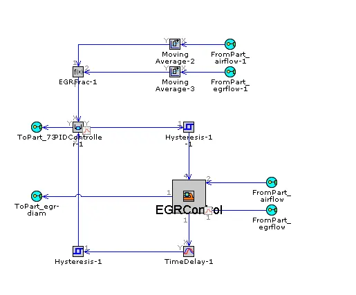
EGR control model
Intercooler model
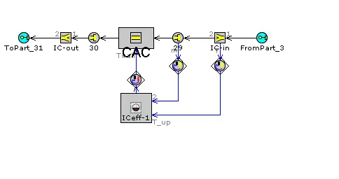
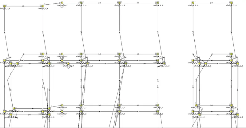
Muffler model
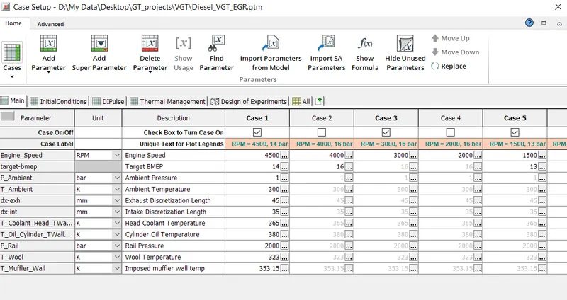
Boundary conditions:
GT POST:
Efficiency of case 1 in compressor map
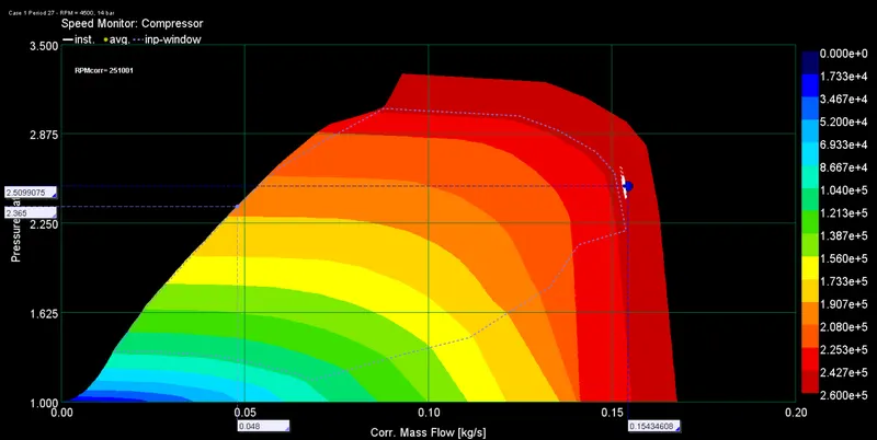
Efficiency of case 2 in compressor map
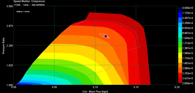
Efficiency of case 3 in compressor map
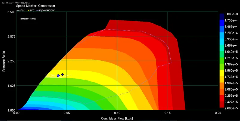
Combined cases in compressor map
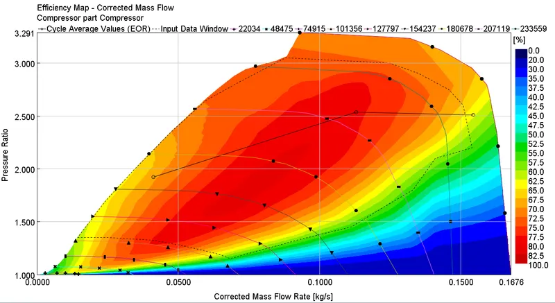
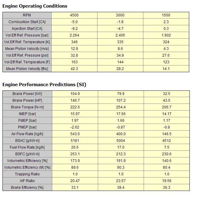
From the compressor map data we see that with decrease in rpm, the design point shift from choke to surge. The optimal point for compressor design is found for 3000 rpm. With reducing rpm, the brake power also reduces and torque also reduces.
Turbine map
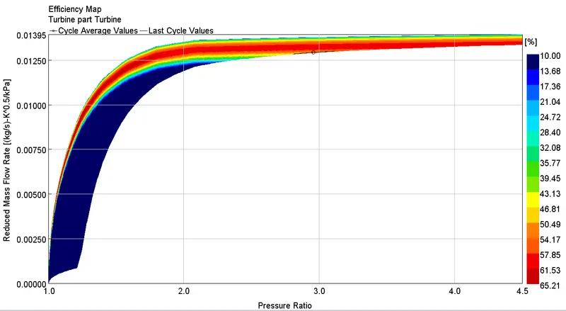
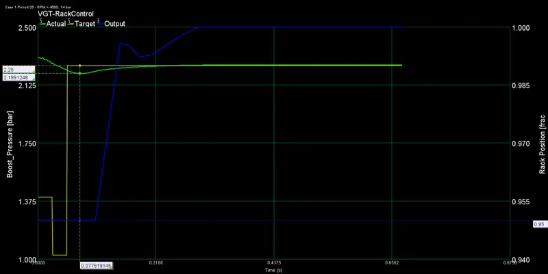
VGT rack control for case1
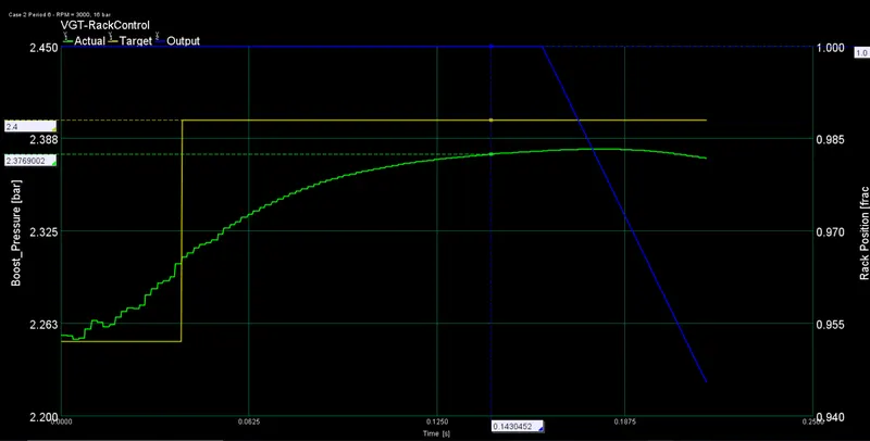
VGT rack control for case2
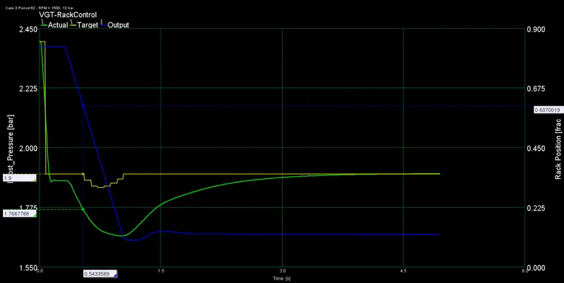
VGT rack control for case3
Engine performance output data
Compressor and turbine output data
In which application Variable Geometry Turbine is beneficial?
The benefits of variable geometry turbines include
- no throttling loss of the wastegate valve;
- higher air–fuel ratio and higher peak torque at low engine speeds;
- improved vehicle accelerations without the need to resort to turbines with high pumping loss at high engine speeds;
- potential for lower engine ΔP (the difference between exhaust manifold and intake manifold pressures);
- control over engine ΔP that can be used to drive EGR flow in diesel engines with High Pressure Loop (HPL) EGR systems;
- a better ability to cover a wider region of low BSFC in the engine speed–load domain;
- ability to provide engine braking;
- ability to raise exhaust temperature for aftertreatment system management.
Conclusions:
- Turbocharger modelling with different models have been studied with different boundary conditions.
- Compressor map model is simulated to study the best design point applicable for running the turbo charger,
- In single TC and Waste gate TC models the efficiency and BP depends upon fuel mass consumption and rpm.