Week-6 : Turbocharger Modelling
- List down different TC and locate examples from GT Power.
Different types of turbochargers are mentioned below:
Single turbocharger:
Single turbochargers can give different torque characteristics by varying the size of compressor wheel. Large turbos will provide high top-end power and smaller turbos will provide better low-end power.
Advantages
- Simple, weight and cost effective.
Disadvantages
- Turbo-lag, narrow effective RPM range.
Twin-turbo:
It means adding a second turbocharger to an engine. It can be used in the case of 6 or 8 cylinder engines.
There are 3 types of turbine setups used for twin turbo setups:
- Parallel
- Sequential
- Series
Advantages
- It gives wider torque range. Less turbo lag.
Disadvantages
- Cost and complexity.
Waste-gate turbocharger:
Waste-gate turbocharger consists of a bypass valve. It vents some part of the exhaust gas going to the turbine and releases them into the outlet. The waste-gate turbocharger has a bypass valve built into the turbine housing. It diverts some of the exhaust gases away from the turbine wheel through this valve. It helps the turbocharger from over running and also prevents mechanical failure.
Advantages
- Reduces turbo lag.
- Compact, optimum engine performance.
Twin-scroll turbocharger:
Advantages
- More energy and power.
- A wider range of RPM and tuning flexibility.
Disadvantages
- Requires a specific exhaust design.
- Cost and complexity.
Variable geometry turbocharger:
VGTs have a ring of aerodynamically-shaped vanes at the turbine inlet and these vanes rotate to vary the gas swirl angle and the cross-sectional area. These vanes alter the turbos area-to-radius (A/R) ratio to match the engines speed. They are typically used in diesel engines than petrol engines because of the complications related to cost and design.
Advantages
- Wide RPM range and compact.
Disadvantages
- Mostly used in diesel applications where exhaust gases are lower so the vanes will not be damaged by heat.
- For gasoline applications, cost typically keeps them out as exotic metals have to be used in order to maintain reliability.
Variable Twin-scroll turbocharger:
A VTS turbocharger has advantages of a twin-scroll turbo and a variable geometry turbo. The VTS turbocharger design provides a cheaper and more robust alternative to VGT turbos, which provides an option for petrol engine applications
Advantages
- Allows for a wide, flat torque curve.
Disadvantages
- Cost and complexity and additional challenges with the technology.
Electric turbocharger:
It can be considered as modern turbocharging. It has an electric motor that spins up the turbo’s compressor from start and through the lower revolutions, until the power from the exhaust volume is high enough to work the turbocharger. It is used to eliminate turbo lag and help a normal turbocharger at lower engine speeds.
Advantages
- Turbo lag and insufficient exhaust gases can be virtually eliminated.
- A wide effective RPM range with even torque.
Disadvantages
- Cost and complexity.
- Packaging and weight.
Examples from GT power:
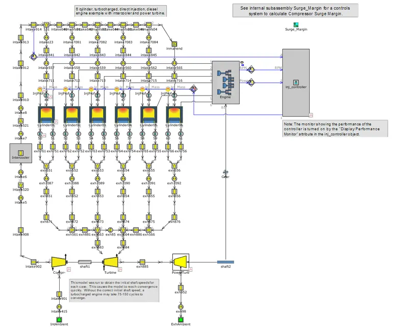
- A simple turbocharger for a 6 cylinder diesel engine with a power turbine. Diesel_6cyl_TC.gtm.
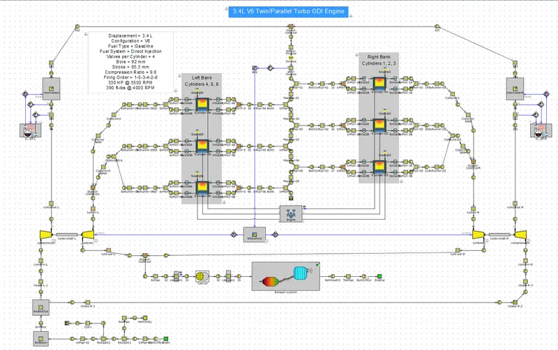
- Twin/parallel turbo gasoline engine.
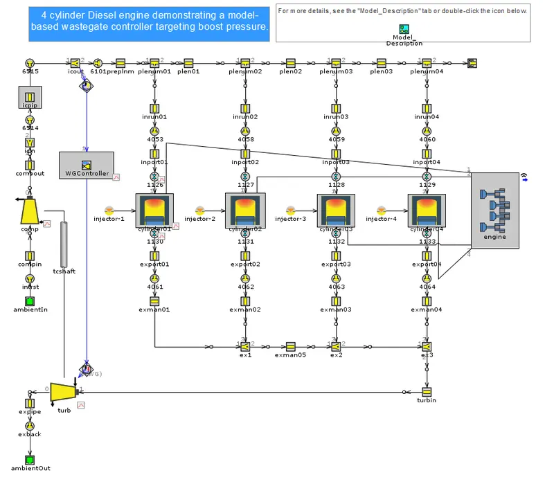
- Turbocharger with waste-gate
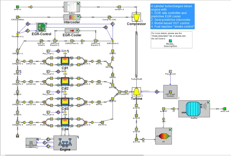
- VGT turbocharger
- Explore tutorial number 6 and 7
Tutotial 6
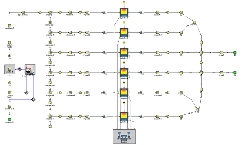
This is a 6 cylinder diesel engine with the end environments at the compressor outlet and turbine inlet, instead of a turbocharger. Here we can give absolute values at the environments according to our requirements. It can also be seen that there are two end environments at the exhaust. This configuration is generally used for an engine with 6 or more cylinders.
The engine geometry and case set up are as follows:
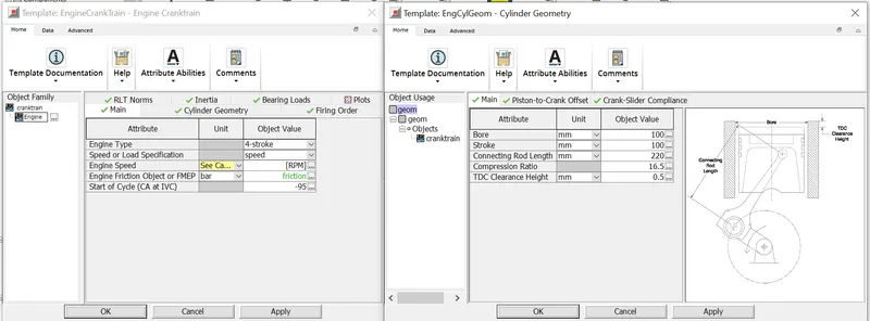
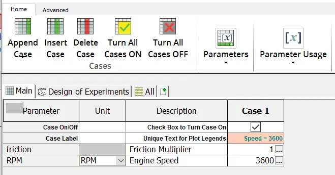
The results for tutorial 6 are as follows:
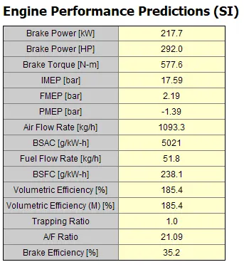
Tutotial 7
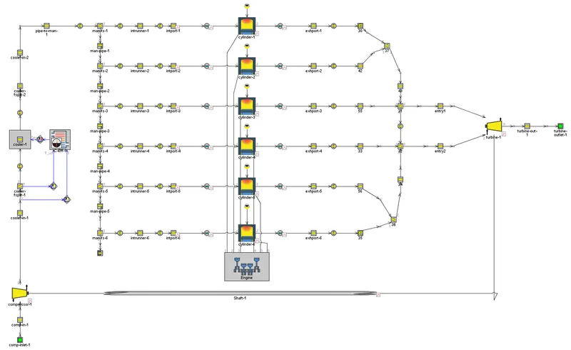
This is a 6 cylinder diesel engine with the end environments at the compressor inlet and turbine outlet, including a turbocharger. Here we can give different compressor and turbine maps according to our requirements. It can also be seen that there are two entries to the turbine at the exhaust manifold.
The engine geometry and case set up are same as tutorial 6. When the model is run for simulation, the results are as follows:
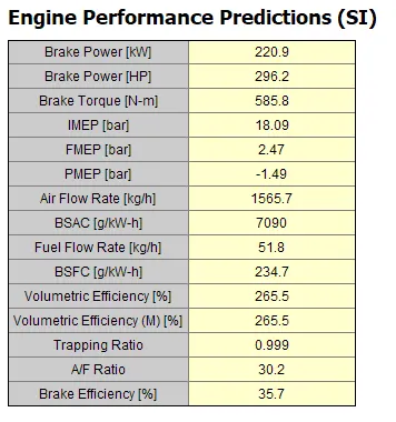
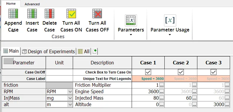
As it can be seen clearly, the engine performance is better when the turbocharger is use instead of end environments. Tutorial 7 can be further explored by changing the injected fuel mass and altitude. As this indirectly changes the intake air requirement and inturn the performance of engine. The case set up has been set as shown below, by decreasing the injected mass flow and increasing the altitude, to see their effect on the engine performance.
The results are as shown below:
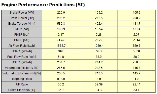
As it can be seen, with the increase in altitude and reduced fuel injected, at the same speed, the brake power, torque, A/F ratio reduced. BSFC is increased. It clearly states that at higher altitute the engine performs well at lower speeds, rather than higher speeds.
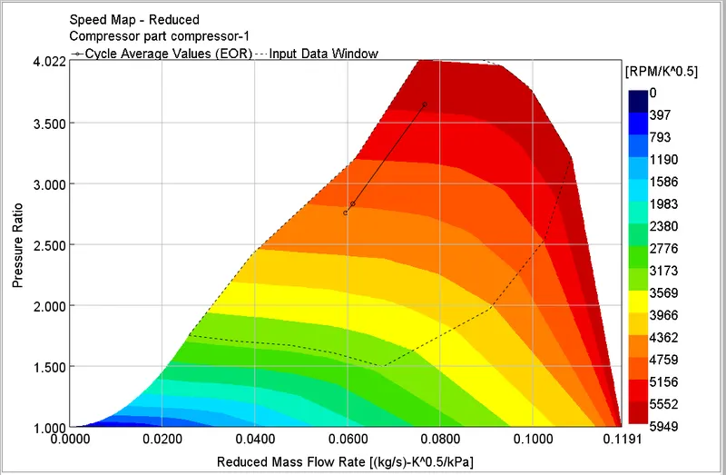
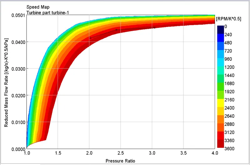
- Plot operating points on compressor and turbine maps
- In which application Variable Geometry Turbine is beneficial?
VGT:
- increases intake air boost pressure at low engine speed and prevents over-boosting at high engine speed
- reduces turbo lag
- improves fuel economy and torque
- is used in applications where different speeds are required with a swift movement. Such applications require less response time. and VGT serves the purpose.
- is typically used in passenger and sports vehicles.
- Explore example- Diesel VGT EGR and understand the modeling part
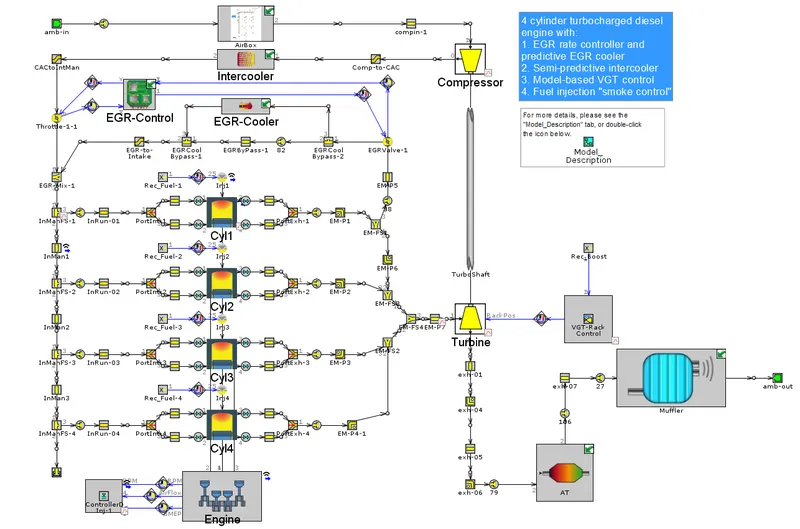
The above figure shows the example of Diesel VGT EGR. The engine model has an EGR cooler, intercooler and few other components along with a variable geometry turbine.
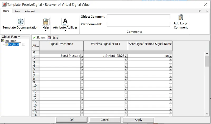
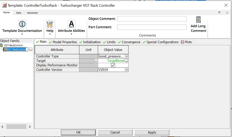
The VGT has a turbine, compressor and a VGT rack control, to which a signal receiver is connected. This signal receiver takes the boost pressure and sends it to the VGT controller, which in turn controls the rack positions in oreder to meet the boost pressure requirements. It is also possible to control the boost pressure with the help of turbine speed instead of rack position. The controlling is done with the help of a PID.
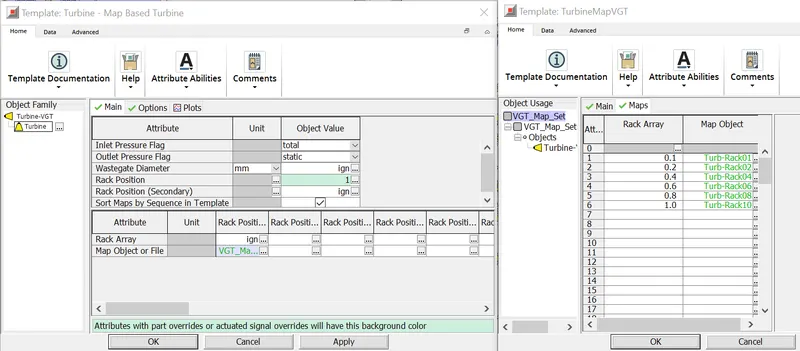
In the turbine, there is a possibility to give turbine map with different rack positions starting from 0.1 ( as the value can't be zero ) and until it is completely open. The limits can be set according to the trend in PID. Once the similation starts, it is possible to monitor the PID. If the PID is unable to reach the target value, it is necessary to modify the limits of rack position.
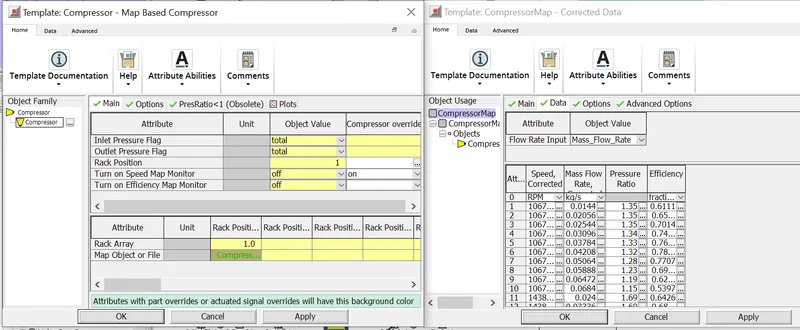
Similarly, compressor has an option to give map manually or in a file format which GT power accepts. GT power has several pre-saved maps in order to practice.