Week 6-Meshing of Hood Challenge
AIM: To create a Mid-surface for given components & to mesh them in a good-looking manner of the element size of 5mm, ensure the given quality criteria were satisfied.
Quality Criteria need to be Satisfy:
| S.N | Quality Criteria | Value |
| 1 | Aspect Ratio | 5 |
| 2 | Skewness | 45 |
| 3 | Warping | 15 |
| 4 | Taper | 0.5 |
| 5 | Min. Length | 2 Units |
| 6 | Max. Length | 8 Units |
| 7 | Min angle Quad | 45 |
| 8 | Max angle Quad | 135 |
| 9 | Min angle Tria | 20 |
| 10 | Max angle Tria | 120 |
| 10 | Tria % | 10 |
PROCEDURE :
1. To assign the value of the given Criteria "Preferences -> Criteria Files -> Input the values".

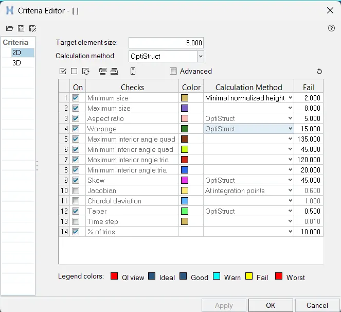
2. Import the model by using the "Import Geometry" option, ensure all the components are available as per the requirement before making taking the Mid-surface/ AutoMesh option,
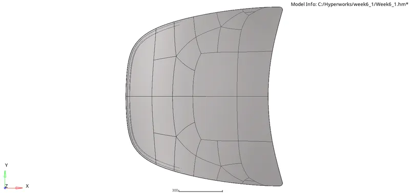
There are 4 Components present in the Hood model:
- Latch
- Hinge
- Outer Body
- Inner Body
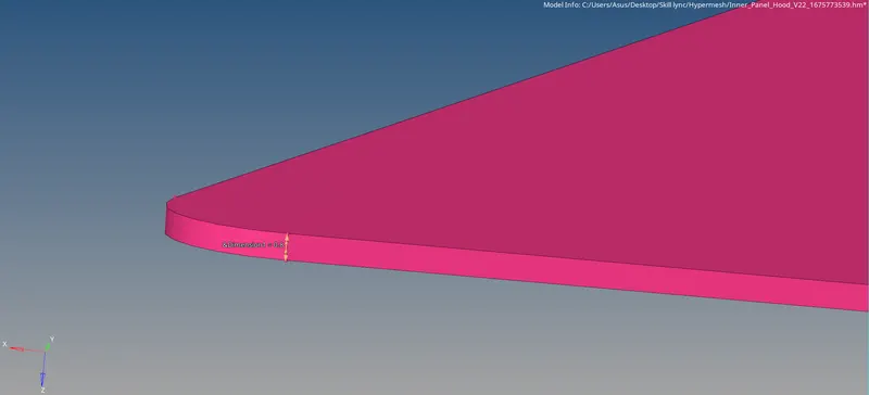
3. Before Extracting the mid surface, if solids are available in the model are need to be deleted using the "Delete" Option by selecting Solids in it.
4. Geometry cleanup of the model is done using the autocleanup command in the "Geometry" window.

5. To create a Midsurface on the component we have to choose " Geom -> Midsurface -> Extraction options -> Offset+Planes".
Once the extraction of the Mid-surface in the Model, Now turn off the Surface of the Inner extract body to show up the mid-surface of the model.
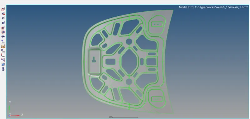
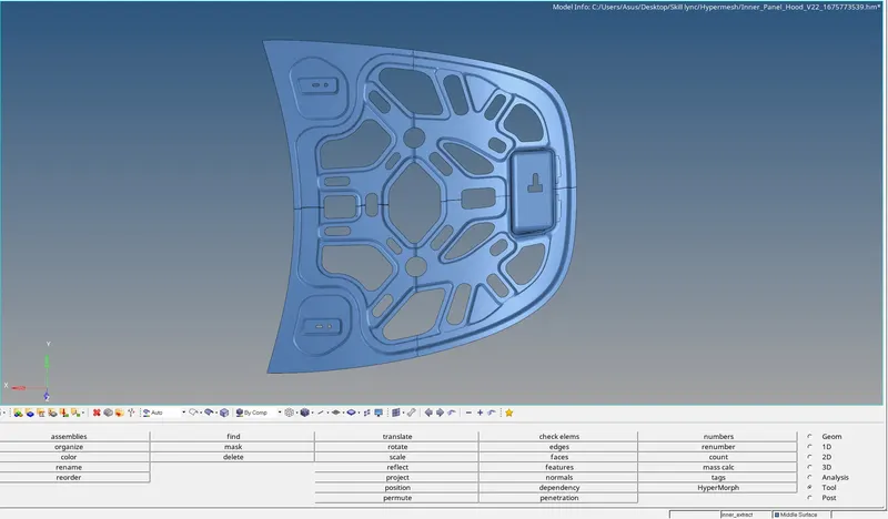
6. Since the model is symmetric the model is splitted in the middle as shown in the figure below.
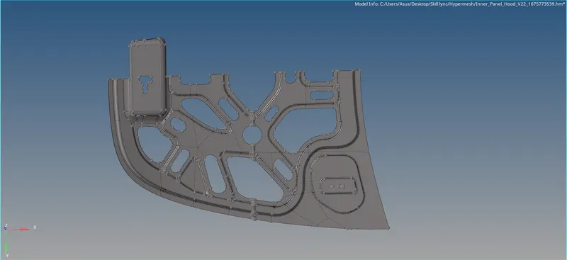
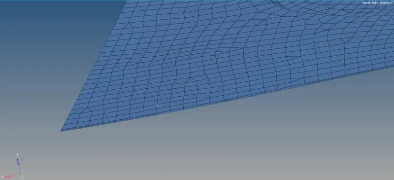
7. To do Mesh on the Component " 2D -> Automesh -> Select the area to be mesh " . To mesh the auto mesh tool in the 2D tab is used which can also be accessed by pressing the F12 key. The element size is changed to 5 and the mesh type is chosen as mixed and the surface to mesh is selected.
The meshing of the surface is done in batches so that proper changes in the number of nodes and quality checks can be done with much less difficulty. When meshing if a tria element is formed it can be removed by either increasing or decreasing the number of nodes under normal circumstances when the surface doesn't have extreme curves.
In some cases when a proper mesh is not attained in such that case we can use "Remesh" Option so that instead of remeshin the whole components by using the "Remesh" option we can built a good mesh flow by the selecting the region that has to be meshed.
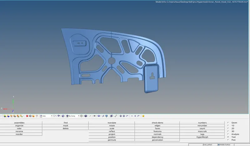
The elements are selected in a way that they form either a square or a rectangle or any closed figure so that a better mesh can be obtained. The selection is shown in the picture below.
8. Due to the component which is shown above is symmetry we can construct half of the geometry for meshing and then using an auto mesh option the mesh can be created. To reflect the component once the meshing is done to the model "Tool -> Reflect -> Select Elems -> Duplicate -> choose the base point" before that make the model as the current component or else the main components will get reflected it.
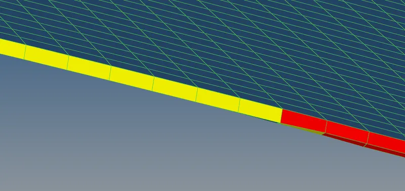
9. After re-meshing, to improve and check the quality of the mesh the 'qualityindex' tool in the 2D tab is used. Elements that are highlighted by selecting the "By Element quality" in yellow and in red are not acceptable and have to be rectified.
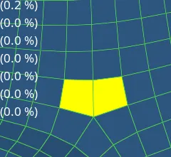
10. The 'element optimize', 'drag tria element', 'place nodes', 'split quad elements', and 'combine tria elements' are the heavily used cleanup tools. The 'drag tria element' is used to move the tria elements in the mesh, two opposite trias can b moved together so that they form a quad element.
The 'place nodes' tool is used to move the nodes of the element so that their shape can be changed or slight adjustments can be made. The 'split quad element' tool is used to split a quad into two trias, this is useful because the trias can be used to form quads in other places. The 'combine tria elements' tool is used to combine two adjacent tria elements, but this can also be achieved by using the 'drag tria element'.
The combined tria element may not satisfy the quality criteria that we have specified and if it doesn't it will be shown in yellow or red as shown in the above picture. This can be easily rectified using the 'element optimizes' tool. In some cases using only the 'element optimize' tool will not work, in those cases, the 'place node' tool is also used to change the position of the nodes and hence the element shape.
After all the elements in yellow and red are rectified by using the cleanup tools or by re-meshing, the 'check elems' tool under the Tool tab is used to check the elements for all the quality criteria individually.

11. To Check the quality of the index of each component are done and pictures of all quality checklist of images are given below.
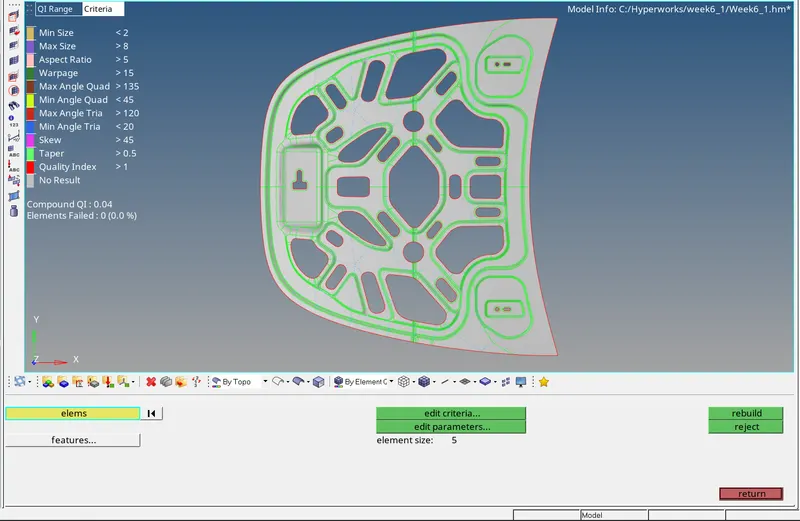
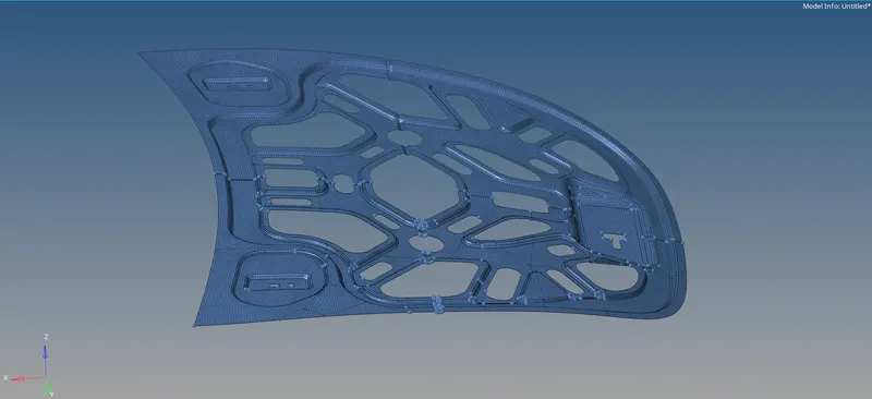
12. Thickness is assigned to the Hood model and the whole component is represented in the 2D detailed view. The final model is represented as shown in the below figure.