Week 6-Meshing of Hood Challenge
Aim:
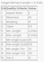
To mesh the given hood model with the following given quality criteria and assign thickness.
Procedure:
1. The given model is opened in hyperworks
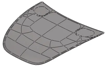
Figure 1 - Given hood model
2. Midsurface generation
The hood model contains four parts. The mid surface for each part is created separately using the below step:
- Select Geometry --> Midsurface --> Auto midsurface --> Auto extraction --> Select surfaces --> Extract
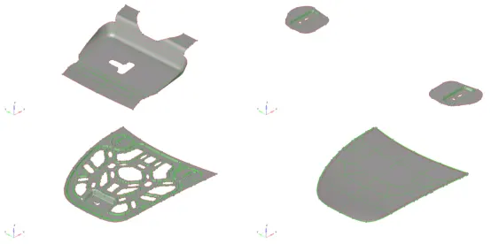
Figure 2 - Midsurface generated
3. Each created midsurfaces are assigned with separate property and same material. This is done as follows:
- In the model browser, right click --> Create --> Material. Enter name as “Material” in properties

Figure 3 - Material creation
-
In the model browser, right click --> select create --> property. Create properties for the 4 parts in the model
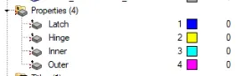
Figure 4 - Property creation
-
Enter thickness values and assign material for each property
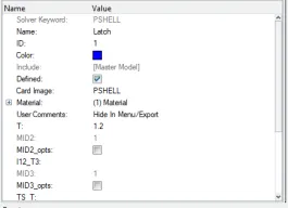
Figure 5 - Thickness and material assignment
- Link property to components
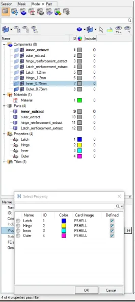
Figure 6 - Link property to components
Geometry cleanup:
- Select Geometry --> Autocleanup --> select Surfaces --> Enter target elem size parameters as “5” in parameters --> Enter the given quality criteria in criteria --> select Autocleanup
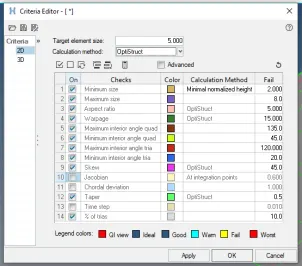
Figure 7 - Enter values in quality criteria
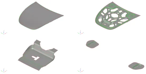
Figure 8 - After geometry cleanup
5. Meshing
- Select 2D --> Automesh --> Enter element size as 5 --> Mesh type as mixed --> select the surfaces to mesh --> Select mesh
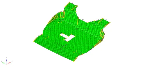
Figure 9 - Meshing of latch reinforcement
By left or right clicking on the number on each edge of the model, the number of mesh points can be increased and decreased to achieve better mesh.
- Next, it is checked if the mesh generated passes the quality criteria. This is checked in the “quality index” option in 2D Tab. This is done as follows:
- The quality parameters entered during autocleanup is present in this option too. By toggling the “fail” option in display threshold, the failed elements are visualized

Figure 10 - Quality index toolbox
-
The elements are cleaned up by using one of the options in the cleanup tools. The tools available are
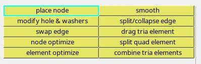
Figure 11 - Cleanup tools
- The final corrected mesh for the component is as follows:
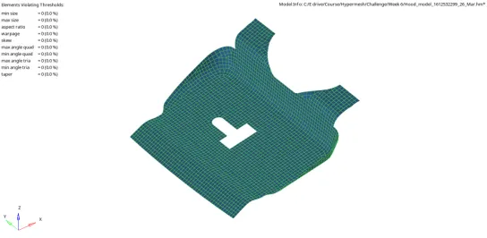
Figure 12 - Final mesh for latch reinforcement
- The quality parameters entered during autocleanup is present in this option too. By toggling the “fail” option in display threshold, the failed elements are visualized
- Similarly, the final corrected mesh for Hinge reinforcement is as follows:
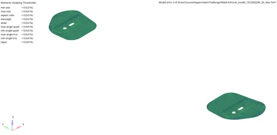
Figure 13 - Final mesh of hinge reinforcement
Meshing of symmetrical components:
The models inner_extract and outer_extract is observed to be symmetric. Hence, the meshing is carried out first only for one half of the model.
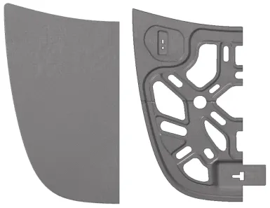
Figure 14 - Meshing one half of model for symmetric components
The mesh generated is checked for the given quality criteria in the qualityindex option and the elements are corrected as discussed above for latch reinforcement.
Next, the second symmetrical half of the mesh is created using the following steps:
- Select Tool --> Reflect --> Elements
- Select the elements to be reflected
- Select the points N1, N2, N3 and B (Base point)
- Select reflect. The reflected model is shown below:
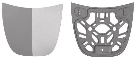
Figure 15 - Symmetrical elements after using reflect option
-
The elements are joined using the equivalence option in Tool --> edges --> select Elements --> Preview equivalence --> select Equivalence
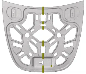
Figure 16 - Join reflected elements using equivalence
-
It is observed that in inner_extract, even after using the equivalence option, the elements are not completely joined in the below mentioned area. This is confirmed using the “find edges” option in Tool --> edges
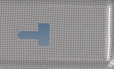
Figure 17 - Presence of free edges
This is cleared by aligning the two nodes by using the command 2D --> Replace --> select the nodes to “Replace” & to be replaced “with”.
Then, the model is checked for free edges using the command Tool --> Edges --> Find edges
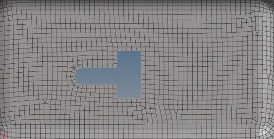
Figure 18 - Corrected mesh -
Next, it is checked for quality criteria failures in the qualityindex option. The final meshed inner & outer extract mesh models are as follows:
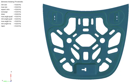
Figure 19 - Final mesh of inner_extract
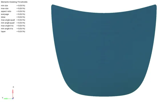
Figure 20 - Final mesh of outer_extract
-
The final meshed model is as follows:
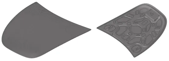
Figure 21 - Final complete meshed model
- The model can be toggled to detailed representation by using the 1D & 2D Detailed Element Representation
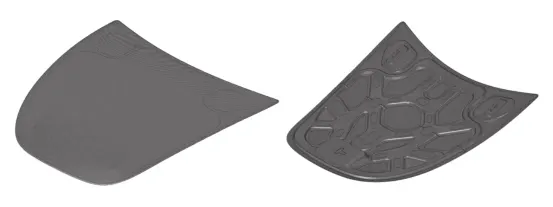
Figure 22 - Detailed representation view of the mesh model
Learning Outcomes:
- Geometry cleanup for components
- Mid surface creation and meshing for uniform wall thickness components
- Correcting the components that fail for the given quality criteria using cleanup tools
- Mirroring of symmetrical mesh elements using reflect option
- Join the mirrored elements using equivalence
Conclusion:
The given hood model is meshed for the following given quality criteria and thickness has been assigned.